
Tube expanding device of tube expander

The technology of a tube expander and a tube expander is applied in the field of processing or metal tube testing and tube expander device, which can solve the problems of unfavorable assembly, complex structure and operation, uneven diameter expansion, etc., to ensure stability and easy operation. , the effect of uniform pressure

Active Publication Date: 2015-01-21
ZHEJIANG DAYANG SEWING MACHINE
View PDF7 Cites 4 Cited by
  • Summary
  • Abstract
  • Description
  • Claims
  • Application Information

AI Technical Summary

Problems solved by technology

The expansion head is usually composed of a ball head with a diameter slightly larger than the inner diameter of the metal tube to be expanded, which is installed on the top of the expansion rod. The tube expansion process is gradual, and the efficiency is low. In addition, the diameter of the beginning of the tube to be expanded is expanded, and the tube wall becomes thinner. , is not conducive to subsequent assembly
In addition, hydraulic tube expansion technology is used, which has the advantages of high tube expansion efficiency, no mechanical damage, and no axial elongation of the tube. However, there is a problem that there is air inside the expanded tube when processing starts. After injecting high-pressure liquid, the internal air and liquid of the expanded tube coexist. When expanding the tube with a thinner tube wall, uneven diameter expansion is likely to occur, which affects the processing quality.
No matter what kind of tube expansion technology is used, the end of the expanded tube needs to be clamped and fixed during the tube expansion process. As disclosed in Chinese patent 201120576598.0, a screw device or a cylinder device is required to lock the jaws. The structure and operations are more complex

Method used


Image

  • Tube expanding device of tube expander
  • Tube expanding device of tube expander
  • Tube expanding device of tube expander

Examples


Embodiment Construction

[0018] Below in conjunction with accompanying drawing, the present invention will be further described:

[0019] In order to clarify the description, the position and direction of the relevant parts are first limited as follows: figure 1 For reference, "inward" refers to the direction toward the center, "outer" refers to the direction toward the left and right ends; "inner" refers to the direction toward the axis, and "outer" refers to the direction toward the top and bottom.

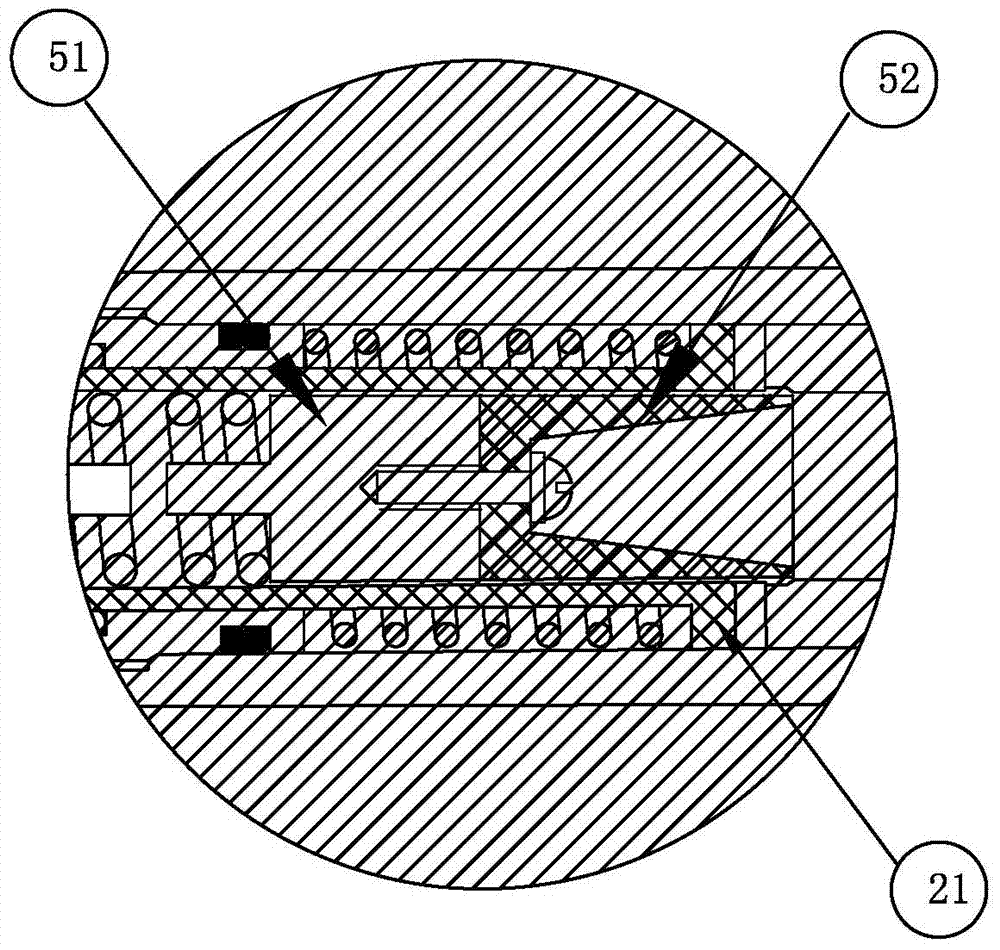
[0020] A tube expander device of a tube expander according to the present invention is composed of a liquid inlet part A' and a fixing seat A, both of which have the same clamping mechanism: the inner ends of the cylindrical shells 1, 1' are equipped with Conical collet 4, 4', the inner end of the cylindrical shell is made into a concave conical surface corresponding to the conical collet, so that the two can slide and fit on the conical surface. When the conical collet retracts, its clamping diameter ...


PUM


Abstract

The invention relates to the technology of tube expanding, in particular to a tube expanding device of a tube expander. The tube expanding device is composed of a liquid inlet part and a fixing seat, and the liquid inlet part and the fixing seat are each provided with a clamping mechanism, In the tube expanding process, the clamping mechanism of the liquid inlet part is fixedly connected with one end of an expanded metal tube in a sealed mode, and the clamping mechanism of the fixing seat is fixedly connected with the other end of the expanded metal tube in a sealed mode. The liquid inlet part and the fixing seat comprise cylindrical actuating rods respectively, an axial liquid inlet channel is arranged in the outer side part of the actuating rod of the liquid inlet part, and an axial exhaust channel is arranged in the outer side part of the actuating rod of the fixing seat. The actuating rod is sleeved with an end cover and is in sliding fit with the end cover. The outer end of the end cover is in threaded fit with the outer end of a cylindrical shell, and flangings are arranged at the inner ends of the actuating rods. The inner side part of the actuating rod of the fixing seat is made to be in a hollow shape, can contain a one-way valve structure and is communicated with the exhaust channel through a one-way valve. According to the tube expanding device, residual air in the expanded tube is exhausted from the exhaust channel, so that the pressure in the expanded tube is even; a tapered clamping head can be automatically locked, the structure is simple, and operation is convenient.

Description

technical field [0001] The invention relates to tube expansion technology, in particular to a tube expander device of a tube expander, which is especially suitable for processing heat exchangers or testing metal tubes. Background technique [0002] Existing tube expanders are mostly used in the processing of heat exchangers. The expansion head is driven by a hydraulic pressure or a motor to radially expand the heat transfer tubes equipped with heat sinks to form an interference fit, so as to achieve a firm combination of heat sinks or tube plates and heat transfer tubes. the goal of. The expansion head is usually composed of a ball head with a diameter slightly larger than the inner diameter of the metal tube to be expanded, which is installed on the top of the expansion rod. The tube expansion process is gradual, and the efficiency is low. In addition, the diameter of the beginning of the tube to be expanded is expanded, and the tube wall becomes thinner. , which is not co...

Claims


Application Information

Patent Timeline
Patent Type & Authority Applications(China)
IPC IPC(8): B21D39/08B21D26/033B21D53/06
CPCB21D26/033B21D39/08B21D53/06
Inventor 曹忠泉黄海君
Owner ZHEJIANG DAYANG SEWING MACHINE
Learn More