IC pin correction device and correction method

A technology for calibrating devices and pins, applied to electrical components, electrical components, etc., can solve the problems of easy finger injury and pain, low processing efficiency, and laborious removal of buckles, so as to simplify processing procedures, improve processing efficiency, and reduce work. the effect of strength

Inactive Publication Date: 2015-01-14
GREE ELECTRIC APPLIANCES INC
View PDF4 Cites 2 Cited by
  • Summary
  • Abstract
  • Description
  • Claims
  • Application Information

AI Technical Summary

Problems solved by technology

This method has the following disadvantages: it is very laborious to pull out the buckle, and the fingers need to be pressed firmly when sealing the buckle, the fingers are easily injured and painful, the labor intensity is high, and the employees are prone to fatigue
At the same time, the processing procedures are complicated and the processing efficiency is low

Method used


Image

  • IC pin correction device and correction method
  • IC pin correction device and correction method
  • IC pin correction device and correction method

Examples


Embodiment Construction

[0042] In order to make the object, technical solution and advantages of the present invention clearer, the IC pin calibration device and calibration method of the present invention will be further described in detail below in conjunction with the accompanying drawings and embodiments. It should be understood that the specific embodiments described here are only used to explain the present invention, not to limit the present invention.

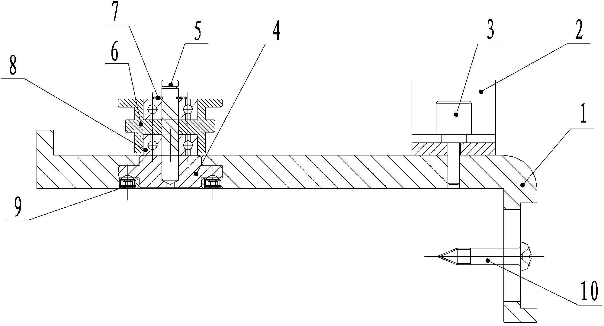
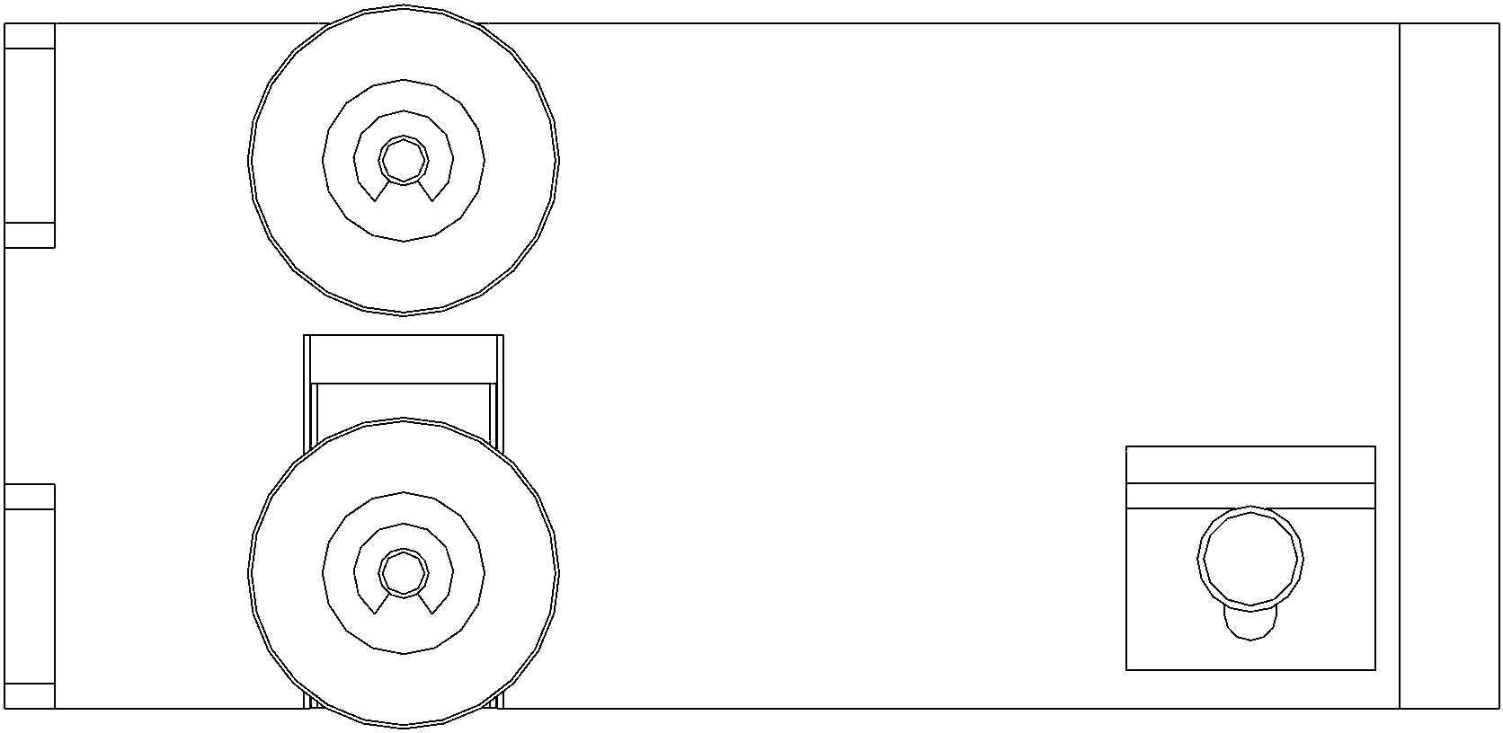
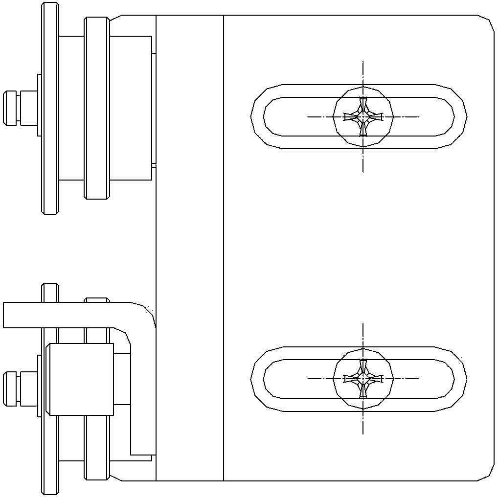
[0043] refer to Figure 1 to Figure 4 , an embodiment of the IC pin correcting device of the present invention comprises a bottom plate support 1, a first shaft 5, a second shaft 13, a first bearing 8, a second bearing 12 and a moving sleeve movable part 4, and a bottom support 1 is L-shaped, fixed on the edge of the workbench by screws 10 or bolts, and used to support the turnover pipe; preferably, the side part of the bottom plate support is adjustable on the side of the workbench.

[0044] The movable sleeve movable part 4 is adjustably ar...


PUM


Abstract

The invention provides an IC pin correction device which comprises a bottom plate piece support, a first shaft rod, a second shaft rod, a first bearing, a second bearing and a movable shaft sleeve movable piece. The movable shaft sleeve movable piece is adjustably arranged on the bottom plate piece support, the first shaft rod is arranged on the movable shaft sleeve movable piece, and the second shaft rod is arranged on the bottom plate piece support. The first bearing is arranged on the first shaft rod, the second bearing is arranged on the second shaft rod, and when a material transfer pipe containing ICs passes between the first bearing and the second bearing, IC pins are corrected. The invention further relates to a correction method of the IC pin correction device. According to the IC pin correction device and the correction method, the processing procedure is simplified, processing efficiency is improved, product quality consistency is improved, the work intensity of operators is obviously reduced, the operators are prevented from being hurt, and the safety of the IC pin correction device and the correction method is increased.

Description

technical field [0001] The invention relates to an IC pin correction process tooling, in particular to an IC pin correction device and a correction method. Background technique [0002] At present, in the electronics industry, IC (Integrated Circuit, integrated circuit board) pin spacing specifications produced by different manufacturers are not uniform, resulting in ICs needing to be processed to a uniform pin spacing before use before being provided to the production line. The processing of IC pins is currently realized by a component pin forming machine. The employee holds the IC turnover tube to pull out the buckle at one end, and then aligns the nozzle with the processing pipe of the machine, tilts the turnover tube, one by one The IC slides down into the processing pipeline using gravity. In the other hand hold an empty turnover tube ready to receive the processed ICs at the other end of the pipeline. After the IC of a turnover tube is processed, the buckle needs to ...

Claims


Application Information

Patent Timeline
Patent Type & Authority Applications(China)
IPC IPC(8): H05K13/00
Inventor 黄锐刘桂李欣阳
Owner GREE ELECTRIC APPLIANCES INC
Why Eureka
Try Eureka