
Fluorescent rotating wheel heat dissipating module of laser projection system

A heat dissipation module and laser projection technology, applied in optics, instruments, projection devices, etc., can solve the problems of increasing the volume of the laser projection system, the inability to increase the motor speed, and the inability to effectively drive the airflow and heat dissipation effect.

Active Publication Date: 2015-01-14
DELTA ELECTRONICS INC
View PDF6 Cites 6 Cited by
  • Summary
  • Abstract
  • Description
  • Claims
  • Application Information

AI Technical Summary

Problems solved by technology

However, as the brightness requirements of optical products continue to increase, the energy of the laser light source must also increase accordingly. In order to meet the brightness requirements, the original metal turntable can only continue to increase the area to further increase the irradiation path of the fluorescent agent. In order to maintain the specific energy required by the fluorescent agent per unit time
[0003] However, this traditional method of enlarging the metal turntable will bring the following problems. One is that when the metal turntable is enlarged, the space of the overall laser projection system must be increased accordingly, which will lead to the increase of the entire laser projection system. The volume of the system increases; the second is that when the metal turntable is enlarged, it means that its high-speed motor must also be upgraded to maintain its high speed. However, when the area of ​​the metal turntable increases, the metal The balance of the turntable is not easy to achieve, and it is difficult to find a matching high-standard motor on the market at present. Therefore, if a high-standard motor with a metal turntable with an enlarged area is required, further development of related motor products is required. In addition, when the motor speed increases, there is also the problem of noise
Furthermore, if the aforementioned problems cannot be solved, and the laser projection system is limited by the size of the metal turntable and the limitations of the motor, the traditional laser projection system will not be able to use a higher-energy laser light source to increase brightness. In other words, if If the area of ​​the metal turntable cannot be increased and the speed of the motor cannot be increased, the brightness of the laser projection system will be limited accordingly
[0004] What's more, even if the speed of the motor driving the metal turntable can be improved, the traditional metal turntable is only a disc-shaped structure, which is not easy to drive the surrounding air to form a high and low pressure difference when rotating, so it cannot effectively drive the airflow to achieve heat dissipation Effect

Method used


Image

  • Fluorescent rotating wheel heat dissipating module of laser projection system
  • Fluorescent rotating wheel heat dissipating module of laser projection system
  • Fluorescent rotating wheel heat dissipating module of laser projection system

Examples


Embodiment Construction

[0033] Some typical embodiments embodying the features and advantages of the present invention will be described in detail in the description in the following paragraphs. It should be understood that the present invention can have various changes in different aspects, but all of them do not depart from the scope of the present invention, and the description and drawings therein are used for illustration in nature, not for limiting the present invention. invention.

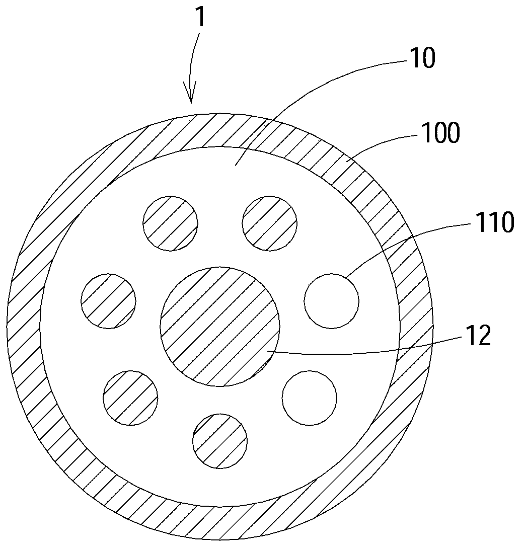
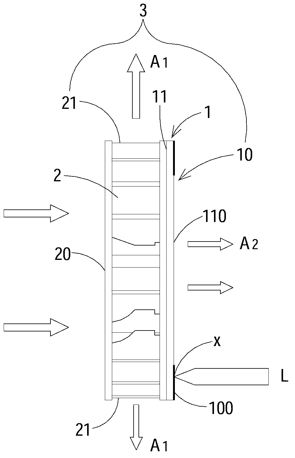
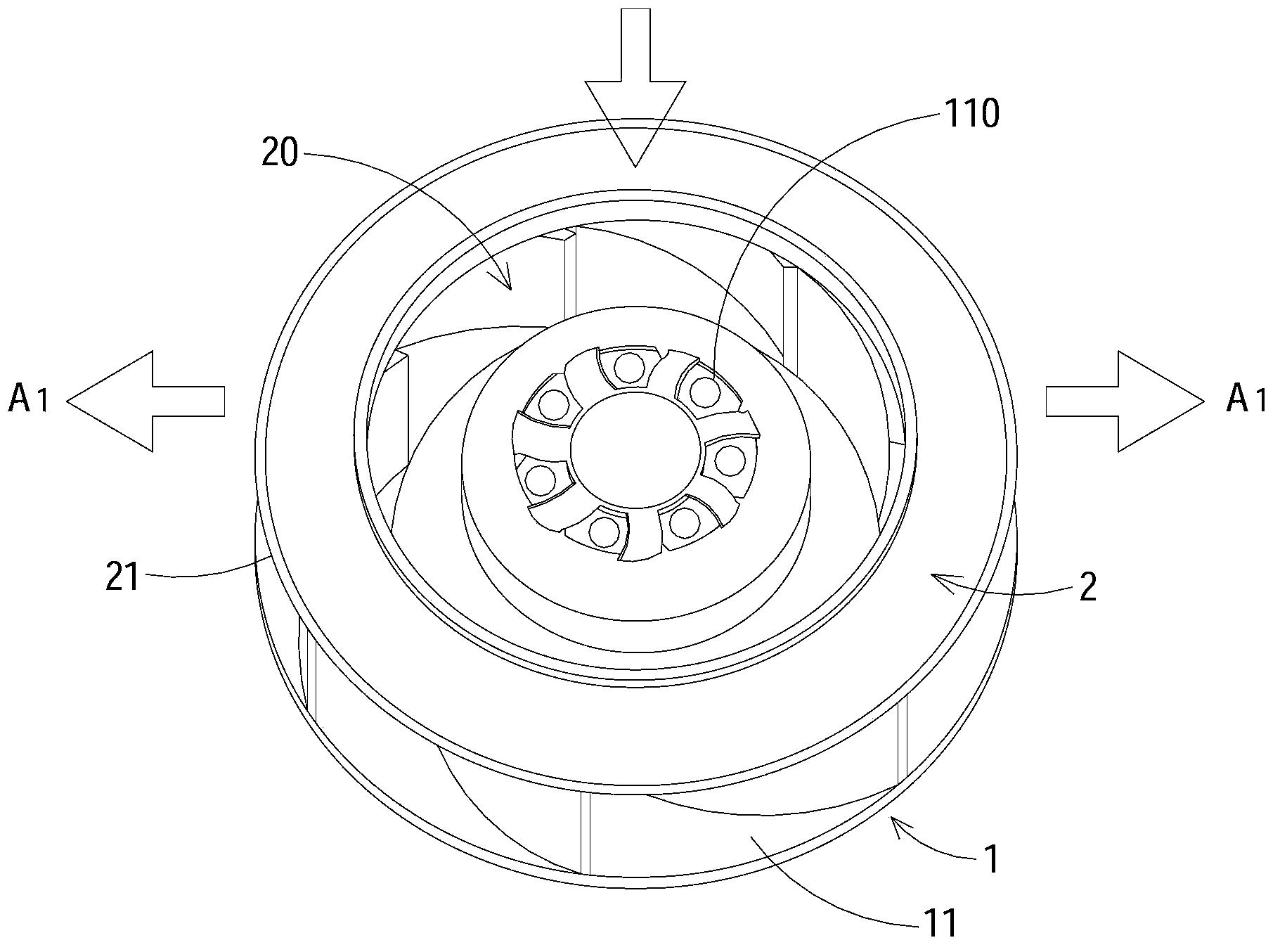
[0034] Please also see Figure 1A , Figure 1B , Figure 1A It is a structural schematic diagram of the first surface of the fluorescent wheel cooling module according to the first preferred embodiment of the present invention, Figure 1B It is a side view structural schematic diagram of the fluorescent runner cooling module of the first preferred embodiment of the present invention. Such as Figure 1A , Figure 1B As shown, the fluorescent wheel heat dissipation module 3 of the present invention is suitable for...


PUM


Abstract

The invention provides a fluorescent rotating wheel heat dissipating module of a laser projection system. The fluorescent rotating wheel heat dissipating module of the laser projection system comprises a fluorescent rotating wheel, multiple air guide holes and blades. The fluorescent rotating wheel is provided with a first surface and a second surface opposite to the first surface. An outer fluorescent ring is arranged on the periphery of the first surface. The air guide holes penetrate through the first surface and the second surface of the fluorescent rotating wheel. The blades are arranged on the second surface of the fluorescent rotating wheel and are provided with an air inlet and first air outlets. A laser source of the laser projection system is projected at a fixed point on the outer fluorescent ring, when the fluorescent rotating wheel rotates, the blades guide airflow to enter from the air inlet of the blades, part of the airflow flows out from the first air outlets of the blades laterally, part of the airflow passes through the second surface via the air guide holes to flow to the first surface, and then heat dissipation is carried out on the fluorescent rotating wheel and the outer fluorescent ring.

Description

technical field [0001] The invention relates to a fluorescent runner cooling module, in particular to a fluorescent runner cooling module which is suitable for a laser projection system and can effectively reduce the local temperature of the fluorescent runner. Background technique [0002] In today's laser projection system, the laser (laser) light source is mainly used to excite the phosphor to generate colored light of different wavelengths. However, in the technical application of this field, due to the high energy and high concentration of the laser, Therefore, the temperature of thousands of degrees can be reached in a short period of time, and it is easy to burn the fluorescent agent. Therefore, the current known method is to coat a fluorescent agent on the outer ring of a metal turntable (phosphor wheel), and use a motor to drive the metal turntable to rotate at a high speed, so that the energy received by the phosphor wheel in a unit time is reduced. And achieve th...

Claims


Application Information

Patent Timeline
IPC IPC(8): G03B21/16
CPCG03B21/16
Inventor 王晖雄沙宇轩
Owner DELTA ELECTRONICS INC
Learn More