Handheld Fiber Optic Coupler and How to Use It

A fiber optic coupler and hand-held technology, applied in the mechanical field, can solve problems such as project quality degradation, inability to obtain test data, and inaccurate fiber cores, and achieve the effects of speeding up construction, reducing costs, and increasing benefits

Inactive Publication Date: 2016-10-12
中邮建技术有限公司
View PDF5 Cites 0 Cited by
  • Summary
  • Abstract
  • Description
  • Claims
  • Application Information

AI Technical Summary

Problems solved by technology

[0003] Compared with one-handed operation, the existing fiber coupler is bulky and heavy, and must be placed on the operating table for operation. The current alignment of the fiber slot is "aimed" by the eyes, resulting in the "misalignment" of the fiber core and the use efficiency. Low, when using a fusion splicer to splice the fibers, it is time-consuming and laborious, and the slow construction speed leads to an increase in cost
For special scenarios such as corridors and poles in fiber-to-the-home projects or harsh scenarios, construction personnel cannot complete the test work, so they can only give up the test and cannot obtain the required test data, resulting in a decline in project quality

Method used


Image

  • Handheld Fiber Optic Coupler and How to Use It
  • Handheld Fiber Optic Coupler and How to Use It
  • Handheld Fiber Optic Coupler and How to Use It

Examples


Embodiment 1

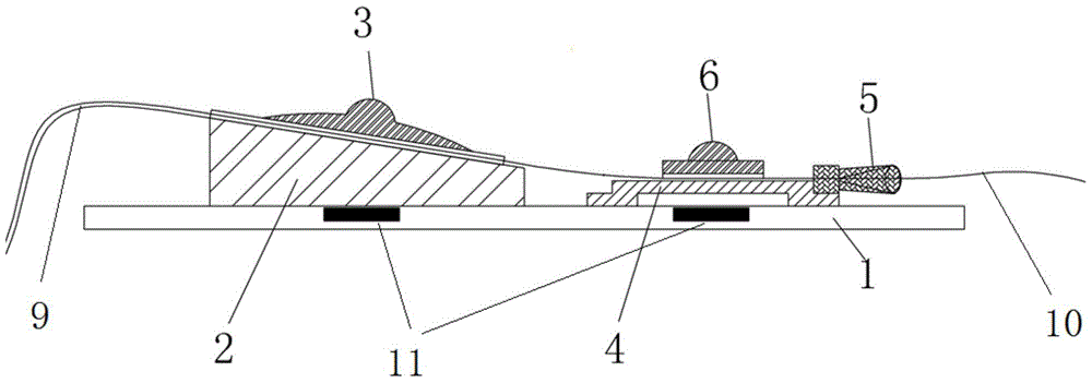
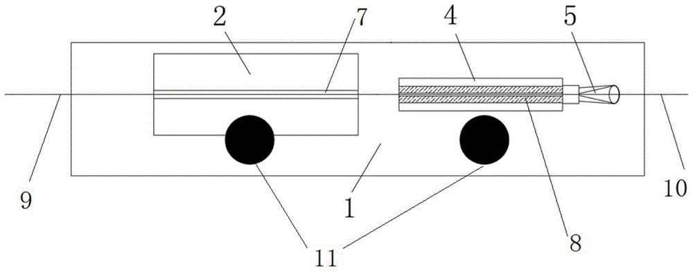
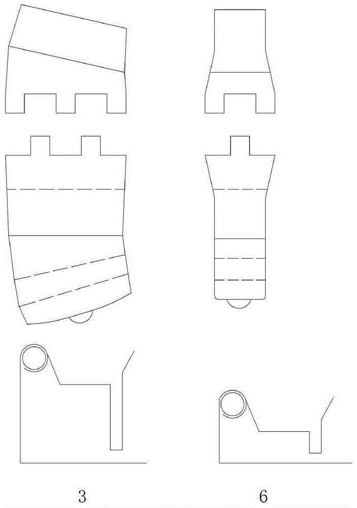
[0041] Such as figure 1 , 2 , 3, the coupler is composed of base 1 made of epoxy resin board, pigtail table 2 made of plastic block, pigtail board 3, coupling body 4, fiber guide hole 5 and fiber board 6, the tail The fiber platform 2 , the fiber pigtail board 3 , the coupling body 4 , the fiber board 6 and the magnet 11 are fixed on the base 1 . Base 1 is 70mm long and 20mm wide.

[0042] The fiber pigtail table 2 has a width of 10 mm and a length of 30 mm. The height of one end close to the coupling body 4 is 3 mm, and the height of the other end is 7 mm. A shallow groove 7 with a depth of 0.5 mm is provided on the central axis of the pigtail stand 2 , and the fiber tail 9 penetrates through the shallow groove 7 .

[0043] The fiber guide hole 5 is connected with the coupling body 4, and the coupling body 4 is provided with a coupling slot 8 for coupling on the central axis. One side of the coupling slot 8 faces the pigtail table 2, and the other side faces the fiber guid...

Embodiment 2

[0046] Such as Figure 5 As shown, the present embodiment is used for single-pan test construction, and its construction method includes the following steps:

[0047] The first step: find out the optical fiber 10 under test;

[0048] Strip the single-reel test optical cable, take out the tested optical fiber 10, which is 1 meter long, remove the coating layer of the optical fiber with a blade, and prepare the end face for future use.

[0049] The second step: connect the pigtail 9 and the test instrument;

[0050]Take out the single-ended pigtail 9 for testing, and connect the flange head side of the single-ended pigtail 9 to the test instrument. Turn on the instrument and adjust it to the real-time state. The other side of the test single-ended pigtail 9 is removed with a blade for 15 cm of optical fiber coating, and the end face is prepared. Put the prepared pigtail 9 into the pigtail table 2 from the left side of the fiber coupler, and the head of the pigtail 9 needs to...

Embodiment 3

[0062] Such as Figure 5 As shown, the present embodiment is used for obstacle checking in optical cable construction, and its specific construction method includes the following steps:

[0063] The first step: find out the optical fiber 10 under test;

[0064] Open the optical cable splice box, find out the optical fiber corresponding to the obstacle optical fiber number, remove the fusion splicing point, take out the tested optical fiber 10 with a length of 1 meter, remove the coating layer of the optical fiber with a blade, and prepare the end face for use. Obstruction points may be on either side of the test point.

[0065] The second step: connect the pigtail 9 and the test instrument;

[0066] Take out the single-ended pigtail 9 for testing, and connect the flange head side of the single-ended pigtail 9 to the test instrument. Turn on the instrument and adjust it to the real-time state. The other side of the test single-ended pigtail 9 is removed with a blade for 15 ...


PUM


Abstract

The invention belongs to the technical field of machines and discloses a handheld optical fiber coupler and an application method thereof to solve the problems that an existing optical fiber coupler is large in size, heavy and low in using efficiency and consumes time and labor. The optical fiber coupler is composed of a base, a tail fiber table, a tail fiber pressing plate, a coupling body, a fiber guiding hole, a fiber pressing plate and magnets. A shallow groove is formed in the central axis of the tail fiber table. A coupling groove is formed in the central axis of the coupling body. A tail fiber and a measured optical fiber are connected in the coupling groove, the tail fiber pressing plate and the fiber pressing plate are iron pressing plates, and the magnets are arranged at the contact position of the tail fiber pressing plate and the base and the contact position of the fiber pressing plate and the base. The invention further provides the application method of the handheld optical fiber coupler. The optical fiber coupler can be handheld to be operated due to the small size, and is suitable for various construction environments, the labor intensity of constructors is lowered, and the optical fiber coupler can be applied to the field of single-deck testing construction, optical fiber construction fault checking and the like.

Description

technical field [0001] The invention relates to a hand-held optical fiber coupler and a using method thereof, belonging to the technical field of machinery. Background technique [0002] With the continuous development of the national fiber-to-the-home project and overseas optical cable communication projects, the construction links such as single-disc detection, detection within 72 hours after deployment, real-time monitoring of connection, and cable obstacle search in the optical cable line project need to be completed using optical fiber couplers. The fiber core of the tested fiber optic cable is coupled and connected with the fiber core of the test fiber, and then the performance test of the fiber optic cable is completed by using the test instrument. [0003] Compared with single-handed operation, the existing fiber coupler is bulky and heavy, and must be placed on the operating table for operation. The current alignment of the fiber slot is "aimed" by the eyes, resulti...

Claims


Application Information

Patent Timeline
Patent Type & Authority Patents(China)
IPC IPC(8): G02B6/38H04B10/07
CPCG02B6/3898H04B10/07
Inventor 殷鹏王亚东吴旌
Owner 中邮建技术有限公司
Why Eureka
Try Eureka