
A Design Method for Fault Diagnosis of Distributed Flight Control System Based on Multi-Agent Technology

A flight control system and fault diagnosis technology, applied in the field of multi-agent systems, can solve the problems of not considering the transmission characteristics of the system to the energy bounded signal, not applicable to the diagnosis of topological communication error information, and the limitation of application scope.

Active Publication Date: 2017-03-01
NANJING UNIV OF AERONAUTICS & ASTRONAUTICS
View PDF5 Cites 0 Cited by
  • Summary
  • Abstract
  • Description
  • Claims
  • Application Information

AI Technical Summary

Problems solved by technology

However, this method still has the following shortcomings: First, this method is designed for a single aircraft to design a fault diagnosis algorithm, which is not suitable for the situation where multiple follower systems fail simultaneously when multiple aircraft are flying cooperatively; The equation only uses the measurement output data of a single aircraft, and does not construct a global error equation based on the connection graph. It is not suitable for the diagnosis of the topological communication error information between multiple follower systems when they fly together; the third is that the method is Designed based on robust H∞ performance, without considering the transfer characteristics of the system to energy-bounded signals, so the application range is greatly limited

Method used


Image

  • A Design Method for Fault Diagnosis of Distributed Flight Control System Based on Multi-Agent Technology
  • A Design Method for Fault Diagnosis of Distributed Flight Control System Based on Multi-Agent Technology
  • A Design Method for Fault Diagnosis of Distributed Flight Control System Based on Multi-Agent Technology

Examples


Embodiment I

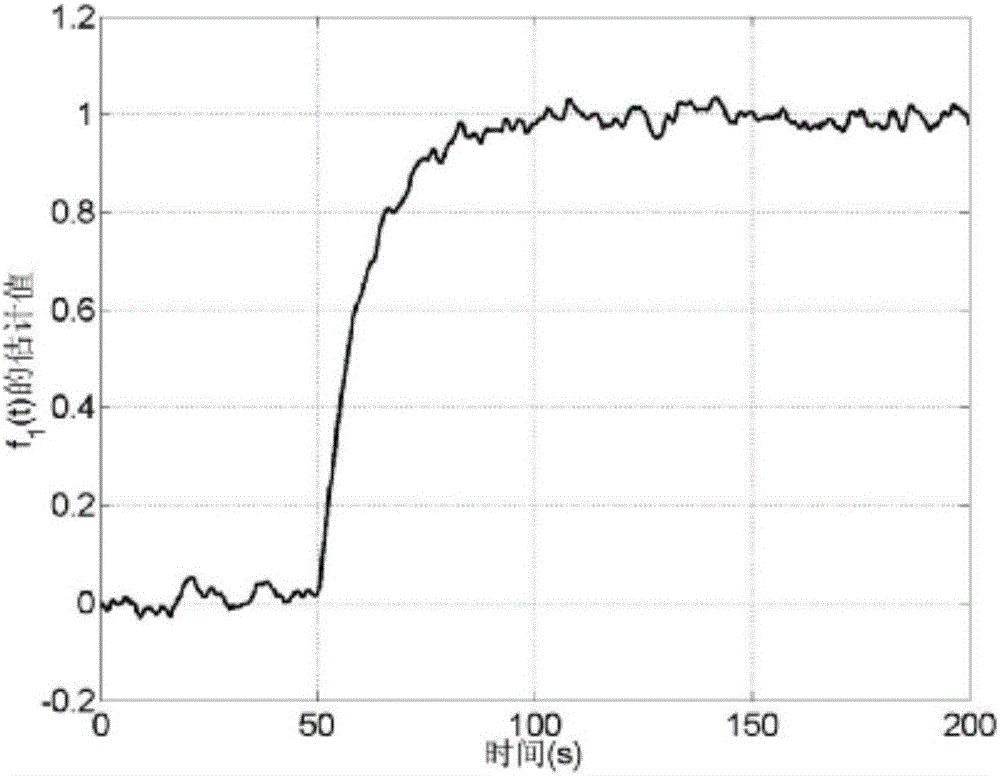
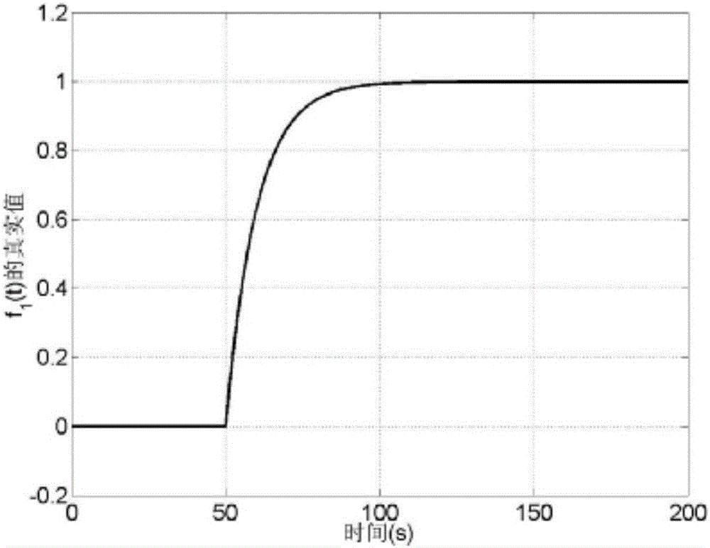
[0088] Simulation example I: Assume that only the first follower node has the following executor failure f(t)=[f 1 (t), f 2 (t)] T :

[0089]

[0090] That is, at 50s, the actuator failure was added to the collective variable.

Embodiment II

[0091] Simulation Example II: Assume that the 3rd and 4th follower nodes fail at the same time, respectively as follows:

[0092] The failure of the third follower node:

[0093]

[0094] Failure of the 4th follower node:

[0095]

[0096] That is, the third follower node added the actuator fault to the longitudinal periodic pitch change at 70s, and the fourth follower node added the actuator fault to the collective pitch variable at 50s.

[0097] As shown in Figure 2, only the first follower node system failure in simulation I is the estimated curve, where: diagram 2-1 is f 1 (t) fault estimation curve, Figure 2-2 is the fault f 1 (t) the true value.

[0098] For simulation II, when the third and fourth follower node systems have actuator failures at the same time, as shown in Figure 3, it is the actuator failure estimation curve of follower node 3, where: Figure 3-1 is f 2 (t) fault estimation curve, Figure 3-2 is the fault f 2 The actual value of (t); as ...


PUM


Abstract

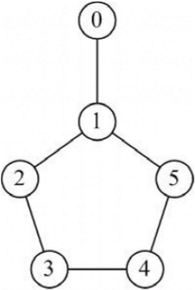
The invention relates to a distributed flight control system fault diagnosis design method based on the multi-agent technology. The method is characterized by including the steps that firstly, a multi-agent system connected graph with a leader is established and represented through an undirected graph and a Laplacian matrix L is acquired; secondly, a state equation and an output equation of each node of a flight control system are established; thirdly, according to each node, a distributed error equation and a global error equation based on the undirected graph are established; fourthly, according to the established undirected graph, the collected state equations of the flight control system, the collected output equations of the flight control system, and the established global error equations, a distributed fault diagnosis observer gain matrix of the flight control system can be acquired. According to the method, a multi-target distributed fault diagnosis observer is designed, online diagnosis can be conducted when any node in the system breaks down or multiple nodes break down simultaneously, and online fault diagnosis and real-time fault estimation can be conducted on the flight control system.

Description

technical field [0001] The invention belongs to the technical field of multi-agent systems, in particular to a method for fault diagnosis and design of a distributed flight control system based on multi-agent technology. Background technique [0002] Multi-Agent Systems (MAS) refers to a system composed of a series of individuals with local perception capabilities, limited processing capabilities, and mutual communication capabilities. Individuals in the system can communicate with other individuals and use their respective capabilities to cooperate with each other to achieve a common goal. There are many systems in nature that can be regarded as multi-agent systems, such as aircraft formation flight, distributed computing, robot collaboration, etc. In recent years, the control problem of multi-agent systems has been paid more and more attention by researchers. The perception and execution capabilities of a single aircraft are limited. For example, in the face of some rela...

Claims


Application Information

Patent Timeline
Patent Type & Authority Patents(China)
IPC IPC(8): G05B23/02
CPCG05B23/0205
Inventor 张柯姜斌徐锦法
Owner NANJING UNIV OF AERONAUTICS & ASTRONAUTICS
Learn More