
Irregularly-shaped rotary heat pipe applicable to various rotation speeds

A rotary heat pipe technology, applied in indirect heat exchangers, lighting and heating equipment, etc., can solve the problems of large material consumption, non-reflux of liquid, and low heat exchange efficiency

Inactive Publication Date: 2015-01-07
NANJING UNIV OF TECH
View PDF5 Cites 16 Cited by
  • Summary
  • Abstract
  • Description
  • Claims
  • Application Information

AI Technical Summary

Problems solved by technology

Therefore, general reactors are equipped with heat exchange jackets, and large reactors or large heat exchange capacity reactors also have built-in coil or straight tube heat exchange components, but these technologies have the problems of low heat exchange efficiency and large material consumption
And because the heat exchange equipment is still inside the equipment, the heat transfer effect is poor, and more heat exchange area is required, which causes waste of reaction space, and also makes the temperature field of the reaction medium not uniform enough, making it difficult to accurately control the temperature
Invention patent "A Dynamic Heat Pipe Stirring Bioreactor for Multiple Biological Reactions" (CN 101182458) discloses a dynamic heat pipe stirring reactor for biological reactions, which solves the problem of enhanced heat transfer at low rotational speeds , but when the stirring shaft reaches a certain speed, the centrifugal force generated by the internal working medium due to the rotation makes the working fluid return operation line in the heat pipe uncertain, and there will be great defects in practical applications, especially when the rotating speed is high, the liquid There is basically no backflow, which will cause the heat pipe to fail. In addition, the cooling section of the heat pipe does not have a clear and feasible sealing structure, so that the water cooling method stays at the scheme stage

Method used


Image

  • Irregularly-shaped rotary heat pipe applicable to various rotation speeds
  • Irregularly-shaped rotary heat pipe applicable to various rotation speeds
  • Irregularly-shaped rotary heat pipe applicable to various rotation speeds

Examples


Embodiment

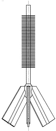
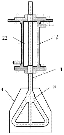
[0024] Such as Figure 1A and 1B As shown, a special-shaped rotating heat pipe suitable for various rotation speeds includes a heat pipe main body 1, the upper section of the heat pipe main body is a heat pipe cooling section 2, the lower section of the heat pipe main body is a heat pipe evaporation section 3, and the outer surface of the heat pipe cooling section 2 is provided with Fin21. The outer side of the heat pipe evaporation section 3 may be provided with a paddle layer 4 (abbreviated as heat absorbing pipe hereinafter).

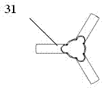
[0025] Such as Figure 2A As shown, the heat pipe evaporating section 3 is provided with three heat absorbing pipes 31. The heat absorbing pipes 31 are evenly distributed around the heat pipe main body 1 and extend sideways and downwards. The outer surface of the heat absorbing pipes 31 is provided with ribs 4 to form blades.

[0026] Such as Figure 2B As shown, the heat pipe evaporating section 3 is provided with four heat absorbing pipes 31. Th...


PUM


Abstract

The invention discloses an irregularly-shaped rotary heat pipe applicable to various rotation speeds. The heat pipe comprises a heat pipe main body, wherein the lower section of the heat pipe main body is a heat pipe evaporation section; the upper section of the heat pipe main body is a heat pipe cooling section; a condensate reflow structure is machined on the inner wall of the heat pipe; the lower end of the heat pipe evaporation section is provided with at least one branch layer; each branch layer is provided with at least two dendritic heat absorbing pipes; the heat absorbing pipes are uniformly distributed by taking the heat pipe main body as the center and extend towards the side lower part; the outer surfaces of the heat absorbing pipes are provided with ribs to form blades. Under the condition that the evaporation section of the heat pipe type stirring paddle is at a lower rotation speed, the gravity is used as main power for reflow of a working medium. Under the condition of higher rotation speed, centrifugal force produced by rotation is used as main power for reflow, so that the heat pipe type stirring paddle has excellent adaptability at various rotation speeds.

Description

technical field [0001] The invention relates to the field of heat pipe stirring bioreactors, in particular to a rotating heat pipe used for high temperature uniformity and high temperature control accuracy. Background technique [0002] Biological and chemical reactors usually need to export heat to control the temperature inside the reactor, and at the same time stir to make it mix well and the temperature is uniform. Therefore, general reactors are equipped with heat exchange jackets, and large reactors or large heat exchange capacity reactors also have built-in coil or straight tube heat exchange components, but these technologies have the problems of low heat exchange efficiency and large material consumption . And because the heat exchange equipment is static inside the equipment, the heat transfer effect is poor, and more heat exchange area is needed, which causes waste of reaction space, and also makes the temperature field of the reaction medium not uniform enough, ...

Claims


Application Information

Patent Timeline
IPC IPC(8): F28D15/02
Inventor 朱跃钊刘宇轩范红途王银峰陈海军杨丽
Owner NANJING UNIV OF TECH
Learn More