
Low-calorific-value gas radiating tube burner and control method thereof

A technology of radiant tube and low calorific value, applied in the direction of combustion method, burner, combustion type, etc., can solve the impact of radiant tube service life on product production process and quality, the deterioration of radiant tube surface temperature uniformity, and the increase of pollutant discharge Major problems, to achieve the effect of ensuring ignition, ensuring stable combustion, and reducing NOx emissions

Active Publication Date: 2015-01-07
WISDRI WUHAN WIS IND FURNACE
View PDF12 Cites 6 Cited by
  • Summary
  • Abstract
  • Description
  • Claims
  • Application Information

AI Technical Summary

Problems solved by technology

[0003] However, with the domestic demand for burning low calorific value gas, including converter gas, blast furnace gas purified gas, and high-coke mixed gas below 1600kal / m3, the existing radiant tube burner structure is used in the application of low calorific value gas. , there will be many problems such as unstable ignition, reduced combustion power, poor temperature uniformity on the surface of the radiant tube, and increased pollutant emissions, which will affect the service life of the radiant tube, the production process and quality of the product

Method used


Image

  • Low-calorific-value gas radiating tube burner and control method thereof
  • Low-calorific-value gas radiating tube burner and control method thereof
  • Low-calorific-value gas radiating tube burner and control method thereof

Examples


Embodiment Construction

[0027] It should be understood that the specific embodiments described herein are only used to explain the present invention, but not to limit the present invention.

[0028] It should be noted that in the description of the present invention, the terms "horizontal", "vertical", "upper", "lower", "front", "rear", "left", "right", "vertical", The orientation or positional relationship indicated by "horizontal", "top", "bottom", "inner", "outer", etc. is based on the orientation or positional relationship shown in the drawings, and is only for the convenience of describing the present invention and simplifying the description, and It does not indicate or imply that the pointed device or element must have a specific orientation, be constructed and operated in a specific orientation, and therefore cannot be understood as a limitation of the present invention. In addition, the terms "first", "second", etc. are only used for descriptive purposes, and cannot be understood as indicating ...


PUM


Abstract

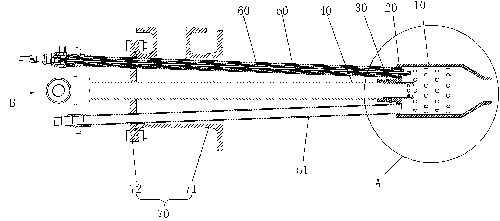
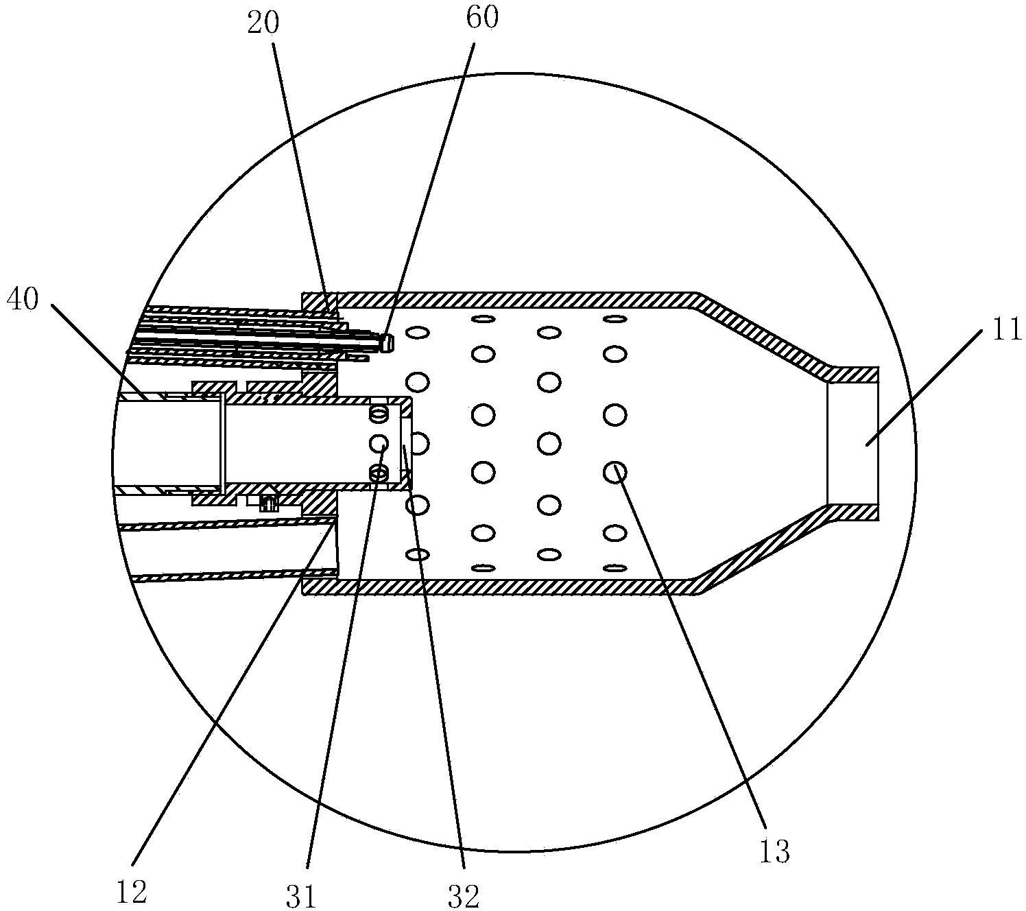
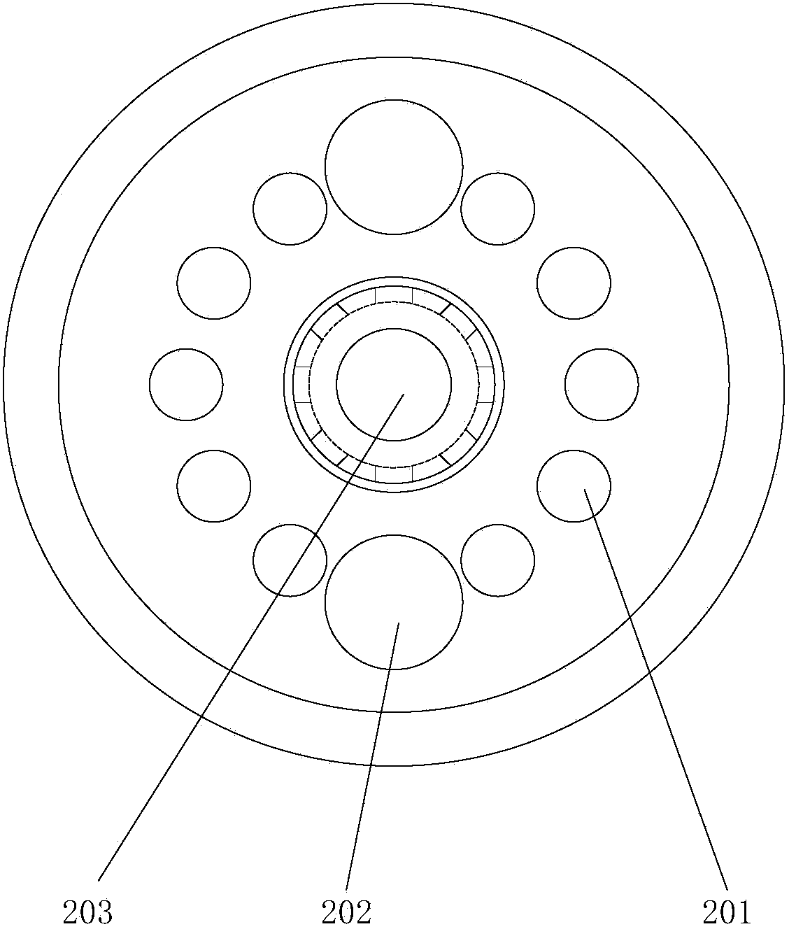
The invention discloses a low-calorific-value gas radiating tube burner. The low-calorific-value gas radiating tube burner comprises a combustion chamber, an air distribution plate, a gas spraying nozzle, a gas guide tube, a first electrode guide tube, an ignition electrode and a fixing device; an inlet of the combustion chamber is provided with the air distribution plate; a combustion cavity of the combustion chamber is communicated with a radiating tube through an outlet of the combustion chamber; the air distribution plate is provided with an air inlet; the first electrode guide tube sleeves the ignition electrode; the first electrode guide tube penetrates the fixing device and the air distribution plate; the gas guide tube penetrates the fixing plate and the air distribution plate; the gas spraying nozzle is arranged at one end of the gas guide tube, wherein the end of the gas guide tube is close to the air distribution plate; the fixing device is used for fixing the low-calorific-value gas radiating tube burner into the radiating tube; the fixing device is provided with a combustion-supporting opening. The invention also provides a control method of the low-calorific-value gas radiating tube burner. According to the low-calorific-value gas radiating tube burner, the ignition stability of the burner during the application of the low-calorific-value gas is improved and meanwhile the emissions of pollutants are reduced.

Description

Technical field [0001] The invention relates to the field of combustion devices, in particular to a low calorific value gas radiant tube burner and a control method thereof. Background technique [0002] In the field of metal heat treatment, with the improvement of product quality requirements, radiant tube heating technology has been widely popularized and applied. In order to meet increasingly stringent production process requirements and pollutant emission requirements, the structural design of the radiant tube burner has been continuously optimized. The performance of the burner in terms of tube surface temperature uniformity, ignition and flame stability, and combustion product NOx control Continuously improving. In terms of gas medium, the current radiant tube burner has been able to adapt to the combustion applications including natural gas, coke oven gas and high coke mixed gas higher than 1800kal / m3. [0003] However, with the increasing domestic demand for burning low-c...

Claims


Application Information

Patent Timeline
IPC IPC(8): F23D14/12F23D14/46F23D14/62F23D14/58F23D14/78
CPCF23D14/12F23D14/46F23D14/58F23D14/62F23D14/78
Inventor 高阳徐少春沈小军
Owner WISDRI WUHAN WIS IND FURNACE
Learn More