Hydraulic system for recycling rotary braking energy and device

A hydraulic system and braking energy technology, applied in the direction of fluid pressure actuating device, fluid pressure actuating system components, servo motor components, etc. Effect

Active Publication Date: 2015-01-07
LIUZHOU LIUGONG EXCAVATORS +2
View PDF6 Cites 10 Cited by
  • Summary
  • Abstract
  • Description
  • Claims
  • Application Information

AI Technical Summary

Problems solved by technology

[0003] The purpose of the present invention is to solve the problem that the rotary braking energy of the current hydraulic excavator cannot be recovered, and proposes a hydraulic system and a hydraulic system that recovers the rotary braking energy and applies the recovered energy to the rotary start. device

Method used


Image

  • Hydraulic system for recycling rotary braking energy and device
  • Hydraulic system for recycling rotary braking energy and device

Examples


Embodiment Construction

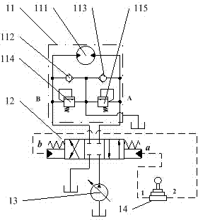
[0020] The hydraulic system 10 of the present invention with recovery of slewing braking energy is as figure 2 As shown, the oil supply ports A and B of the first hydraulically controlled three-position four-way reversing valve 12 are respectively provided with oil supply pipelines connected to the accumulator 16 at the same time, and the first oil supply pipelines are respectively set in each oil supply pipeline. One-way valve 154 and second one-way valve 153 are used to ensure oil supply port A or B to supply oil to the accumulator 16 in one direction, and a hydraulically controlled two-position two-way reversing valve is arranged in the oil supply pipeline of the accumulator 16. The valve 152 is used to switch the oil supply pipeline; the oil supply ports A and B of the first liquid press three-position four-way reversing valve 12 are respectively provided with the second hydraulic control three-position four-way reversing valve 151 The P port of the second hydraulically c...


PUM


Abstract

Disclosed is a hydraulic system for recycling the rotary braking energy. The braking energy of a rotary motor is recycled towards an energy accumulator through a hydraulic control two-position two-way reversing valve; the control oil of a pilot control valve is switched to a corresponding reversing valve for reversing through a first electromagnetic two-position four-way reversing valve and a second electromagnetic two-position four-way reversing valve; the reversing action of the first electromagnetic two-position four-way reversing valve and the second electromagnetic two-position four-way reversing valve is controlled by a controller, wherein the pressure of the energy accumulator is determined through the controller. According to the hydraulic system for recycling the rotary braking energy and a device, the energy recycling and utilization is achieved in a full-automatic mode and the existing hydraulic systems such as the rotary motor and a main control valve do not need to be modified; added elements are less, the technology is mature, and the price is low; only the braking energy of the rotary motor is recycled and the energy output through the existing rotary hydraulic system is not received through the energy accumulator; when the rotary motor is started, the energy of the energy accumulator is utilized first, then the pump output energy is automatically switched and utilized, and accordingly the mutual interference is not produced.

Description

technical field [0001] The invention relates to engineering machinery with a hydraulic slewing system, in particular to a hydraulic system and a device for recovering slewing braking energy. Background technique [0002] In the most common excavation and loading conditions for hydraulic excavators, each cycle has two slewing start and braking processes. Such as figure 1 As shown, the overflow valve is used as the back pressure without exception when the slewing brake is used to decelerate the slewing until it stops. During the braking process, the hydraulic oil overflows through the overflow valve, that is, the kinetic energy of the rotation is converted into the heat energy of the hydraulic oil and consumed. Contents of the invention [0003] The purpose of the present invention is to solve the problem that the rotary braking energy of the current hydraulic excavator cannot be recovered, and proposes a hydraulic system that recovers the rotary braking energy and applie...

Claims


Application Information

Patent Timeline
Patent Type & Authority Applications(China)
IPC IPC(8): F15B13/06F15B1/04
CPCF15B13/06F15B1/04F15B21/14
Inventor 李文新高皓王茄任刘剑李欲江
Owner LIUZHOU LIUGONG EXCAVATORS
Why Eureka
Try Eureka