
Liquid heating machine and power output device

A heating device and liquid technology, applied in the field of power machinery, can solve the problems of fast damage to the shell and transmission parts, high heat medium requirements, poor gas thermal conductivity, etc., and achieve low piston reciprocating operating frequency, low heat medium requirements, and low temperature difference require small effects

Active Publication Date: 2015-01-07
徐承飞
View PDF4 Cites 8 Cited by
  • Summary
  • Abstract
  • Description
  • Claims
  • Application Information

AI Technical Summary

Problems solved by technology

[0002] We know that traditional steam engines and steam turbines are large in size and noisy, and their use is limited
For example, the power plant of a nuclear submarine is generally a steam engine. When submerged in the sea, the noise is not conducive to concealment, and it is not suitable to use loud noise machinery in daily life.
Although the existing Stirling engine solves the noise problem, it uses gas as a working medium. Because the gas has poor thermal conductivity and is easy to be compressed, the Stirling engine has a fast speed but the direct output torque is small, and it cannot directly drive heavy vehicles. Load, and requires a large temperature difference (above 500-700 ℃) to work normally, high heat medium requirements, narrow application range, low efficiency
The external components of the Stirling engine need multiple, rapid and repeated cycles of work in order to output high power externally; the piston, casing and transmission components of the engine are damaged quickly and have a short service life

Method used


Image

  • Liquid heating machine and power output device
  • Liquid heating machine and power output device
  • Liquid heating machine and power output device

Examples


Embodiment 1

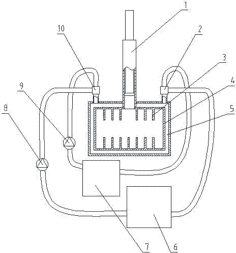
[0019] Such as figure 1 The liquid heat engine shown includes an expansion tank 4 and a single-acting hydraulic cylinder 1. The expansion tank 4 is provided with a heat-expanding liquid working fluid. The hydraulic chamber of the hydraulic cylinder 1 communicates with the inside of the expansion tank 4. Cooling device, as can be seen from the figure, the structure of the working medium heater and the working medium cooler is: a heat exchange chamber 5 is provided on the side wall of the expansion tank, and a heat exchange inlet and a heat exchange outlet are provided on the heat exchange chamber 5. The heat exchange inlet is connected to the heat pump 9 and the cooling pump 8 through the three-way valve 10, the heat pump 9 is connected to the heat source 7, the cooling pump 8 is connected to the cold source 6, and the heat exchange outlet is connected to the heat source 7 and the cold source 6 through the three-way valve 2 connected. The inner wall of the expansion tank 4 is ...

Embodiment 2

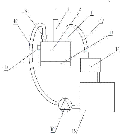
[0022] Such as figure 2 The liquid heat engine shown is characterized in that it includes an expansion tank 4 and a single-acting hydraulic cylinder 1. The expansion tank 4 is provided with a heat-expanding liquid working medium, and the hydraulic cavity of the hydraulic cylinder 1 is connected to the expansion tank 4. A working medium heating device and Working fluid cooling device, from figure 2 It can be seen from the figure that the working medium heating device is provided with a heater 13 at the bottom of the expansion tank, or it can be a heater surrounding the outside of the expansion tank or a heater placed inside the expansion tank, which can quickly heat the liquid working medium. The working fluid cooling device is: a cold liquid tank 15 is provided, and the expansion tank 4 is provided with a liquid inlet and a liquid discharge port. A liquid inlet valve 19 is provided on the liquid port; the liquid discharge port is connected with the cold liquid tank 15 throu...


PUM


Abstract

The invention discloses a liquid heating machine and relates to the technical field of a power machine , and the liquid heating machine comprises an expansion box and a hydraulic cylinder, wherein a thermal expansion liquid working medium is arranged in the expansion box, the hydraulic cavity of the hydraulic cylinder is connected with the expansion box and provided with a working medium heating device and a working medium cooling device. The liquid heating machine is simple in structure, high in direct output torque and efficiency and low in heating medium demand and temperature difference, the heating machine can be normally operated in the temperature difference of 30-50 degrees centigrade, and wide in application range and low in noise, the piston of the hydraulic cylinder has low reciprocating working frequency and fully utilizes enormous pressure occurred due to thermal expansion of the liquid. The liquid heating machine is used to recycle heat energy and converse it into mechanical energy in a vehicle heat removal system, and the mechanical energy can be further conversed into electric energy for storage and utilization.

Description

technical field [0001] The invention relates to the technical field of power machinery, and in detail relates to a liquid heat engine and a power output device with simple structure, large direct output torque, high efficiency and low noise. Background technique [0002] We know that traditional steam engines and steam turbines are large in size and noisy, and their use is limited. For example, the power plant of a nuclear submarine is generally a steam engine. When submerged in the sea, the noise is not conducive to concealment, and it is not suitable to use loud noise machinery in daily life. Although the existing Stirling engine solves the noise problem, it uses gas as a working medium. Because the gas has poor thermal conductivity and is easy to be compressed, although the Stirling engine rotates fast, the direct output torque is small, and it cannot directly drive heavy vehicles. Load, and requires a large temperature difference (above 500-700 ℃) to work normally, high...

Claims


Application Information

Patent Timeline
Patent Type & Authority Applications(China)
IPC IPC(8): F02G5/02F02G1/043F02G1/055
CPCF02G1/043F02G1/055F02G5/02F02G2256/00Y02T10/12
Inventor 徐承飞
Owner 徐承飞
Learn More