A clamping method and clamping device for workpiece clamping

A clamping device and workpiece clamping technology, which is applied in the direction of clamping devices, positioning devices, metal processing machinery parts, etc., can solve the problems of reduced workpiece processing accuracy, time and effort, and difficulty, so as to improve production efficiency, Guaranteed processing accuracy and improved service life

Active Publication Date: 2016-09-07
ZHUZHOU KAIFENG IND
View PDF7 Cites 0 Cited by
  • Summary
  • Abstract
  • Description
  • Claims
  • Application Information

AI Technical Summary

Problems solved by technology

[0004] like figure 2 As shown, during processing, the movable half-mold 6 pushes the workpiece 1 along the inside of the horizontal trough 3 to move from the loading position 4 towards the processing position 7, and when it pushes the workpiece 1 out of the port of the horizontal trough 3 until one side of the workpiece 1 is in contact with the fixed During this period of time when the half-mold 9 is in contact, only one side of the workpiece 1 is in contact with the movable half-mold 6, and its other side is not in contact with the fixed half-mold 9. There will be a tendency to fall down, and the shape of the clamping surface of the movable half-mold 6 and the fixed half-mold 9 (that is, the part where the movable half-mold and the fixed half-mold are in contact with the workpiece) is matched with the workpiece 1 Yes, in order to make the movable half-mold 6 and the fixed half-mold 9 clamp and fix the workpiece 1 so as to facilitate processing, it is necessary to ensure that the workpiece 1 is fully in contact with the clamping surfaces of the movable half-mold 6 and the fixed half-mold 9 when processing, if the workpiece 1 If it falls downward when being pushed out of the horizontal chute 3, the clamping surfaces of the movable half mold 6 and the fixed half mold 9 cannot fully contact the workpiece 1, so that the workpiece 1 cannot be clamped tightly, and normal production cannot be carried out
[0005] Existing flat head chamfering machines for pipe fittings solve the above problems by controlling the moving speed of the movable half-mold 6, utilize the inertia when the workpiece 1 is pushed out of the horizontal trough 3, and move the workpiece by setting the moving speed of the suitable movable half-mold 6 1 is pushed to the clamping surface of the fixed mold half 9 to clamp the workpiece 1 on both sides. Therefore, the setting of the moving speed of the movable mold half 6 is very important. If the moving speed is too slow, the workpiece 1 has not yet Pushed to the clamping surface of the fixed half-mold 9, its inertia has disappeared, and the workpiece will fall; if the moving speed is too fast, the momentum of the workpiece 1 will increase, and its impulse will also increase, thereby affecting the fixed half-mold. The impact force of the mold 9 is also increased. On the one hand, the excessive impact force will cause the workpiece to be crushed and deformed, which will greatly increase the reject rate of the workpiece and increase the production cost. On the other hand, the machining accuracy of the workpiece will also be reduced. A substantial reduction will further increase the scrap rate and production cost of the workpiece; in addition, the processing of the workpiece after being crushed and deformed will also have a great impact on the cutter head, and there will be a problem of cutting the cutter, which requires frequent replacement of the cutter head. Increased production costs and reduced service life of processing equipment
Therefore, before the actual processing, it is difficult to set the moving speed of the movable mold half to an appropriate moving speed according to the specifications of the workpiece, and it takes a lot of time and energy, resulting in a waste of manpower and material resources, especially when processing When the workpiece specifications are different (the specifications of the corresponding movable half mold and fixed half mold are also different), correspondingly, the moving speed of the movable half mold should also be re-adjusted and changed.

Method used


Image

  • A clamping method and clamping device for workpiece clamping
  • A clamping method and clamping device for workpiece clamping
  • A clamping method and clamping device for workpiece clamping

Examples


Embodiment

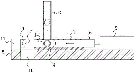
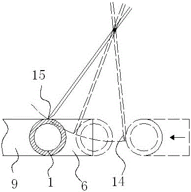
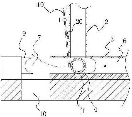
[0040] Example: such as Figure 10 As shown, a clamping method for workpiece clamping, which is to make the workpiece 1 enter the feeding position 4, and then push the workpiece 1 to move towards the fixed half-mold 9 at the processing position through the movable half-mold 6 Finally, through the cooperation of the movable half-mold 6 and the fixed half-mold 9, the movable half-mold 6 and the fixed half-mold 9 are respectively clamped on both sides of the workpiece 1 so as to clamp and fix the workpiece 1 for processing, After the workpiece 1 enters the feeding position, an auxiliary clamping process is added in the process of clamping and fixing the workpiece 1 through the cooperation of the movable half-mold 6 and the fixed half-mold 9, that is, setting a The auxiliary clamping mechanism of the auxiliary clamping part 14, when the movable half mold 6 pushes the workpiece 1 to move towards the fixed half mold 9 at the processing position, the workpiece 1 will be in contact wi...


PUM


Abstract

The invention discloses a clamping method and a clamping device for clamping a workpiece. According to the clamping method, an auxiliary clamping process is added in the process of fixedly clamping the workpiece by matching a movable half mold with a fixed half mold after the workpiece enters a feeding position, namely, an auxiliary clamping mechanism with an auxiliary clamping portion is arranged, the auxiliary clamping portion loosens one side of the workpiece when the workpiece is fixedly clamped as two sides of the workpiece are clamped by the movable half mold and the fixed half mold respectively by matching the movable half mold with the fixed half mold, and the auxiliary clamping process of the workpiece is finished. Difficulty in setting the moving speed of the movable half mold is reduced, manpower and material resources are saved, the workpiece cannot fall off after being pushed out of a horizontal trough, the workpiece cannot be broken by compression deformation, the rejection rate of the workpiece is reduced, and production cost is decreased.

Description

technical field [0001] The invention relates to a clamping method and a clamping device thereof, in particular to a clamping method and a clamping device for workpiece clamping. Background technique [0002] The pipe fitting flat chamfering machine is a processing equipment that uses a power head device with a cutter head to flatten and chamfer the workpiece before leaving the factory. Such as Figure 1 to Figure 3 As shown, the processing process of an existing flat end chamfering machine for pipe fittings is as follows: first, the workpiece 1 is placed in the vertical trough 2, and the workpiece 1 falls from the vertical trough 2 into the horizontal trough 3 and is located Loading position 4 (the loading position is located in the horizontal trough and directly below the vertical trough), and then controls the action of the horizontal air cylinder or hydraulic cylinder 5 to drive the movable half-mold 6 fixedly connected to the piston rod along the horizontal trough. 3. T...

Claims


Application Information

Patent Timeline
Patent Type & Authority Patents(China)
IPC IPC(8): B23Q3/00
CPCB23Q3/08B23Q3/082B23Q7/00B23Q2703/04
Inventor 尹高平韦校飞
Owner ZHUZHOU KAIFENG IND
Why Eureka
Try Eureka