Processing apparatus equipped with catalyst-supporting honeycomb structure, and method for manufacturing same

A technology of a honeycomb structure and a treatment device, which is applied in the directions of catalyst carrier, catalyst activation/preparation, gas treatment, etc., can solve the problems of reducing the contact area of ​​the treated gas, increasing the pressure loss, blocking the mesh of the honeycomb structure, etc. Effects of simple regeneration treatment, prevention of contact area reduction, and low manufacturing cost

Active Publication Date: 2014-12-24
HITACHI ZOSEN CORP
View PDF7 Cites 8 Cited by
  • Summary
  • Abstract
  • Description
  • Claims
  • Application Information

AI Technical Summary

Problems solved by technology

[0005] In addition, in the honeycomb structure formed by laminating and bonding flat plates and corrugated plates alternately, for example, in the purification treatment of exhaust gas, etc., when the gas to be treated contains solid components, solid parts may appear with the passage of time. Phenomenon in which components clog the meshes (voids) of the honeycomb structure
Since the gas to be processed does not come into contact with the inner wall of the mesh blocked by solid components, the contact area of ​​the gas to be processed is reduced
In addition, the pressure loss also increases

Method used


Image

  • Processing apparatus equipped with catalyst-supporting honeycomb structure, and method for manufacturing same
  • Processing apparatus equipped with catalyst-supporting honeycomb structure, and method for manufacturing same
  • Processing apparatus equipped with catalyst-supporting honeycomb structure, and method for manufacturing same

Examples


Embodiment 1

[0095] By the method of the present invention, a denitration catalyst-supporting honeycomb type treatment device is manufactured as follows.

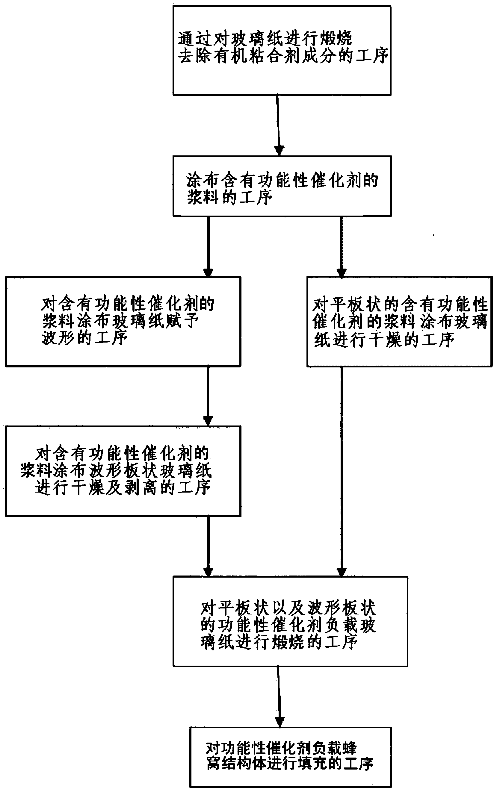
[0096] First, in the method of the present invention, in the process of calcining commercially available cellophane and burning and removing the organic binder component contained in the cellophane, as the commercially available cellophane, organic binder made of acrylic resin is used. Cellophane made of agent. The cellophane is rolled into a roll, and the cellophane with a length of 950 mm is cut from the roll.

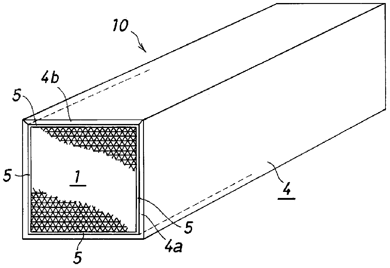
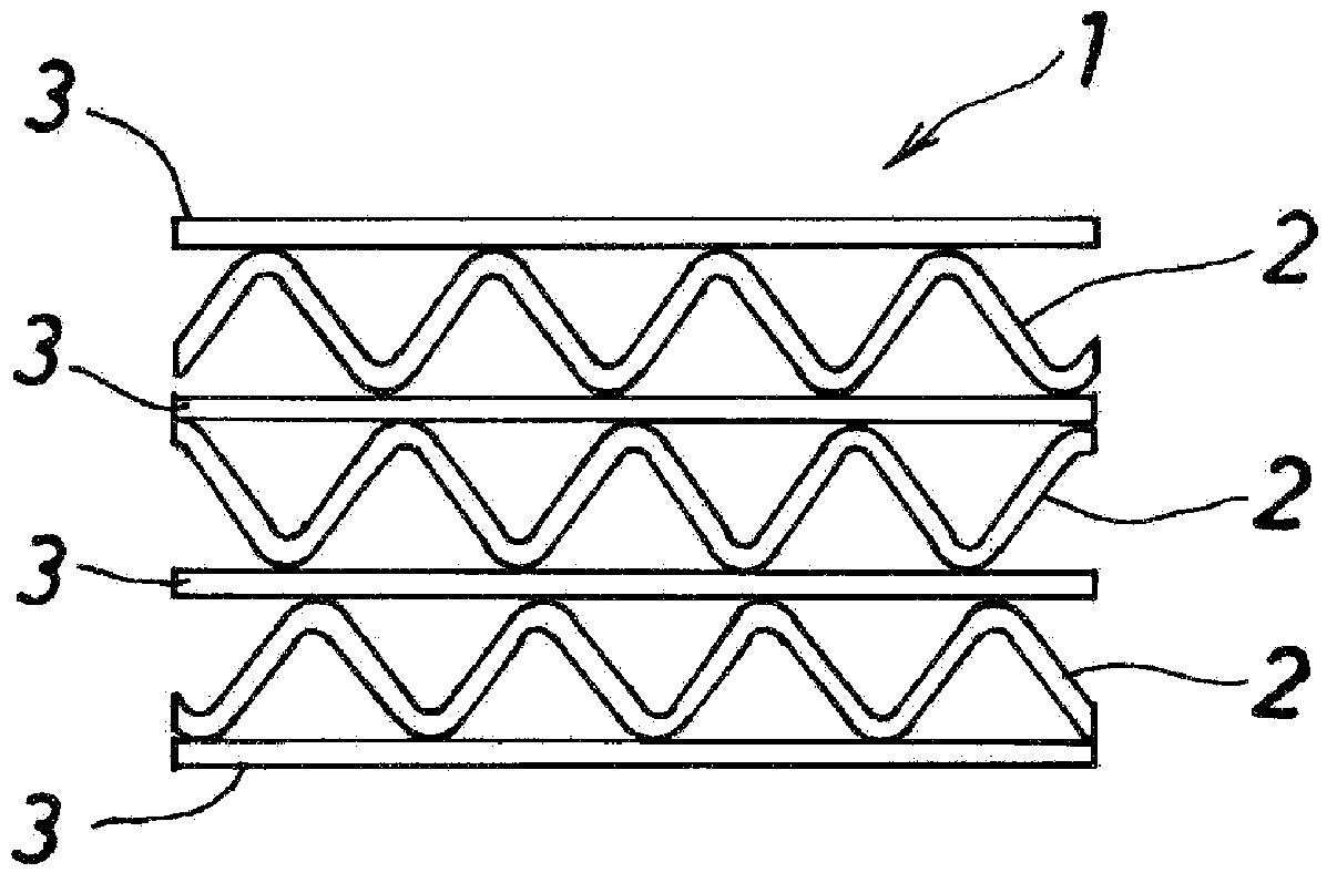
[0097] On the other hand, in order to obtain a flat denitration catalyst-supported cellophane (3) that is not shaped into a corrugated plate, commercially available cellophane is also cut from a roll, but in order to be finally combined with the glass paper that is filled in the angular cylindrical case (4) The corrugated plate-shaped denitration catalyst-supported cellophane (2) is of the same size when viewed from above, an...

Embodiment 2

[0115] Similar to the case of the above-mentioned Example 1, the denitration catalyst-supported honeycomb treatment device (10) was produced by the method of the present invention, but the difference from the case of the above-mentioned Example 1 was the composition of the slurry containing the denitration catalyst.

[0116] That is, 10 g of ammonium metavanadate was added per 1 kg of the slurry to a slurry in which titanium dioxide fine particles were suspended in silica sol (the solid content ratio was 45% by weight, and the ratio of silicon dioxide to titanium dioxide was 20:80). powder, and the whole was stirred for 1 hour, so that the ammonium metavanadate was adsorbed on the titanium dioxide.

[0117] Next, 28 ml of ammonium metatungstate aqueous solution (3.88 mol / L) was further added to the slurry per 1 kg of the slurry, and the whole was stirred for 1 hour.

[0118] A denitration catalyst-supporting honeycomb type treatment device ( 10 ) was produced in the same manne...


PUM


Abstract

To form a catalyst-supporting honeycomb structure using commercially available, inexpensive glass fiber paper as a base material. To provide a processing apparatus equipped with a catalyst-supporting honeycomb structure, as well as a method for manufacturing the same, in which there is no need for large-scale equipment such as a dipping tank or drying device as conventionally used for a catalyst-supporting honeycomb structure, and manufacturing cost is low, and whereby the catalyst-supporting honeycomb structure can easily be regenerated even when cells thereof become clogged with solids from processed gas in an exhaust gas cleaning process or the like, for example, and it is possible to prevent pressure loss from increasing and the surface area of contact with processed gas from decreasing. In a processing apparatus (10) equipped with a catalyst-supporting honeycomb structure, a corrugated glass fiber paper (1) on which a functional catalyst is supported, and a plate-shaped glass fiber paper (2) on which the same functional catalyst is supported are layered so as to be alternately non-bonded to each other, thus forming a catalyst-supporting honeycomb structure (1), and the catalyst-supporting honeycomb structure (1) is packed into a casing (4).

Description

technical field [0001] The present invention relates to a processing device equipped with a catalyst-carrying honeycomb structure and a manufacturing method thereof, which are used, for example, for purification of exhaust gas or production of hydrogen by decomposition of ammonia. Background technique [0002] Conventionally, it has been difficult to use commercially available cellophane as a base material for a honeycomb structure (flat plate + corrugated plate) used in a treatment device equipped with a catalyst-carrying honeycomb structure for exhaust gas purification treatment, etc., and cellophane suitable for wave processing is available in The type is limited (refer to the following Patent Document 1). [0003] And until now, in order to manufacture a treatment device equipped with a catalyst-supported honeycomb structure, the tangent portion of the honeycomb structure, that is, the part where the apex of the corrugated plate contacts the flat plate, is bonded via an ...

Claims


Application Information

Patent Timeline
Patent Type & Authority Applications(China)
IPC IPC(8): B01J23/22B01D53/94B01J23/30B01J33/00B01J35/04F01N3/28
CPCB01J35/04F01N3/2835F01N2330/30B01D53/8631B01D53/8634B01D2255/1026B01D2255/20707B01D2255/20723B01D2255/20776B01D2257/404B01D2257/406B01D2257/2064B01D2257/30Y10T156/1003B29L2031/14Y02E60/36B01J23/22B01J23/30B01J37/02B01J37/08C01B3/047F01N3/28B01D53/885B29D99/0089
Inventor 日数谷进日野尚荣山本诚吾清水香奈
Owner HITACHI ZOSEN CORP
Why Eureka
Try Eureka