
Adjustable positioning milling fixture

An adjustable and clamping technology, applied in positioning devices, clamping, manufacturing tools, etc., can solve the problems of clamping deformation and low production efficiency, and achieve the effect of reliable clamping, high production efficiency and simple structure

Active Publication Date: 2014-12-24
芜湖杰诺瑞汽车电器系统有限公司
View PDF6 Cites 9 Cited by
  • Summary
  • Abstract
  • Description
  • Claims
  • Application Information

AI Technical Summary

Problems solved by technology

[0003] In order to overcome the disadvantages of manual clamping required for processing thin-walled motor casings with existing fixtures, which are prone to clamping deformation and low production efficiency, the present invention provides a fixture whose purpose is to meet the requirements of positioning, reliable clamping and production efficiency , ensure precision, uniform clamping force, will not damage the processed surface, reduce production costs, avoid shell deformation caused by excessive pressure during the clamping process, and can clamp thin-walled motor shells with different diameters or different lengths

Method used


Image

  • Adjustable positioning milling fixture
  • Adjustable positioning milling fixture
  • Adjustable positioning milling fixture

Examples


Embodiment Construction

[0024] The specific implementation manners of the present invention will be described in further detail below with reference to the accompanying drawings.

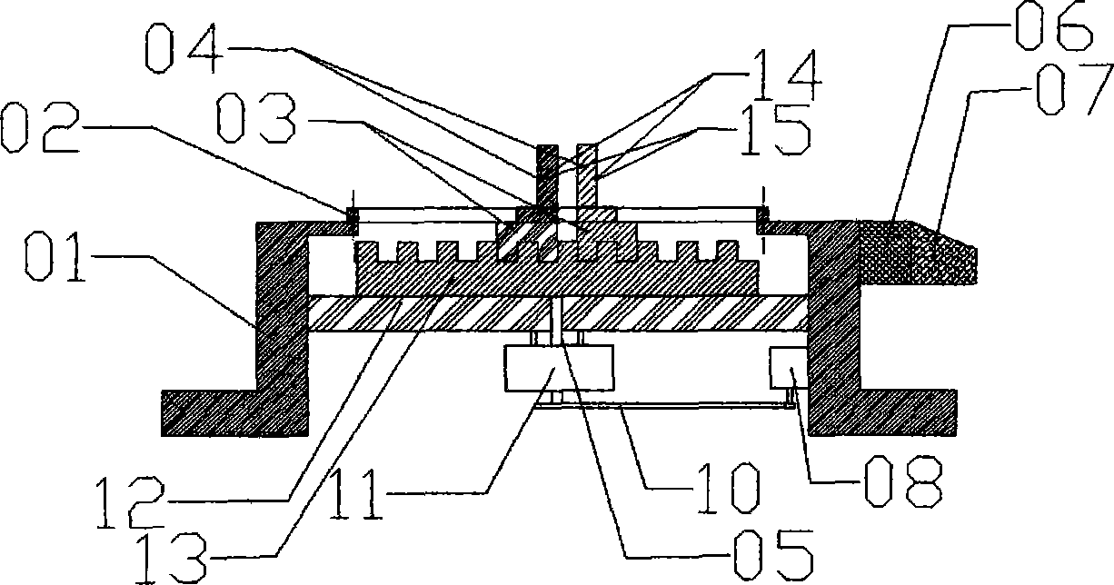
[0025] As shown in the figure, the adjustable positioning milling fixture provided by the present invention includes a fixture body 01, a guide rail 02, a slider 03, a clamping block 04, a shaft 05, a single-chip microcomputer 06, a control panel 07, a motor 08, and a conveyor belt 10. Reducer 11, positioning seat 12, positioning block 13, pressure sensor 14, sensor installation groove 15; there is a sensor installation groove 15 on the side of the clamping block 04 in direct contact with the motor casing, and the pressure sensor 14 is installed on the sensor installation In the groove 15, the clamping block 04 passes through the guide rail 02 and is connected with the slider 03. When clamping thin-walled motor casings with different diameters, in order to make the clamping block 04 and the motor casing tightly fit, you can...


PUM


Abstract

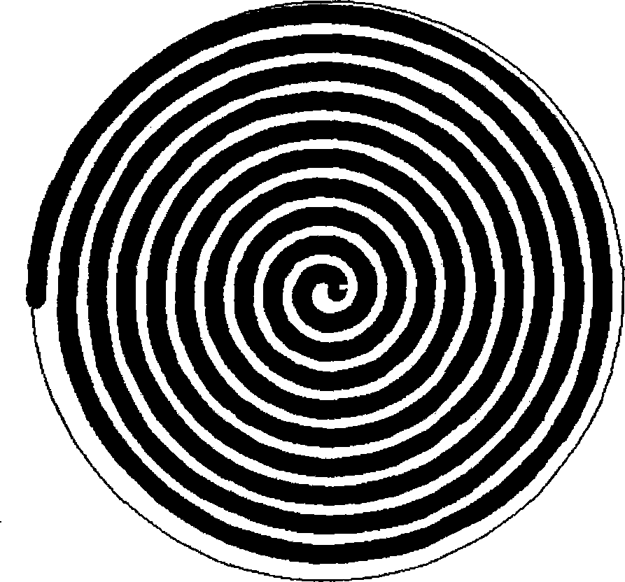
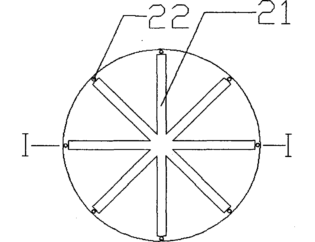
An adjustable positioning milling fixture comprises a fixture body, a guide rail, sliders, clamping blocks, a single-chip processor, a control panel, a motor, a conveying belt, a reducer, a positioning seat, a positioning block, a pressure sensor and a sensor mounting groove. The fixture is mainly used for clamping parts with thin walls and housings. The clamping blocks are capable of moving along the straight guide rail through the spiral rail, straight guide rail and rails at the bottoms of the sliders in a matched manner. The fixture is used for clamping the thin-wall motor housing when the thin-wall motor housing is milled, and the thin-wall motor housing is guaranteed being fixed during machining.

Description

technical field [0001] The invention relates to the field of motor processing, in particular to a milling fixture with adjustable positioning. Background technique [0002] In the field of mechanical processing, the outer circle is often used as the positioning and installation reference for milling grooves of thin-walled motor casings, and most of them are manually clamped. The disadvantages are: easy to produce clamping deformation and low production efficiency. Once the deformation is too large during processing, it will be scrapped, resulting in waste of resources, time and labor. Contents of the invention [0003] In order to overcome the disadvantages of manual clamping required for processing thin-walled motor casings with existing fixtures, which are prone to clamping deformation and low production efficiency, the present invention provides a fixture whose purpose is to meet the requirements of positioning, reliable clamping and production efficiency , to ensure p...

Claims


Application Information

Patent Timeline
Patent Type & Authority Applications(China)
IPC IPC(8): B23Q3/00
CPCB23Q1/25B23Q3/065B23Q17/005
Inventor 曾庆平许其山
Owner 芜湖杰诺瑞汽车电器系统有限公司
Learn More