Sinker electric discharge machining apparatus

一种成型加工、电火花的技术,应用在电动加工设备、附属装置、金属加工设备等方向,能够解决主轴重量增加等问题

Active Publication Date: 2014-12-24
SODICK CO LTD
View PDF8 Cites 0 Cited by
  • Summary
  • Abstract
  • Description
  • Claims
  • Application Information

AI Technical Summary

Problems solved by technology

However, these preventive measures will increase the weight of the spindle, which is not ideal.

Method used


Image

  • Sinker electric discharge machining apparatus
  • Sinker electric discharge machining apparatus
  • Sinker electric discharge machining apparatus

Examples


Embodiment Construction

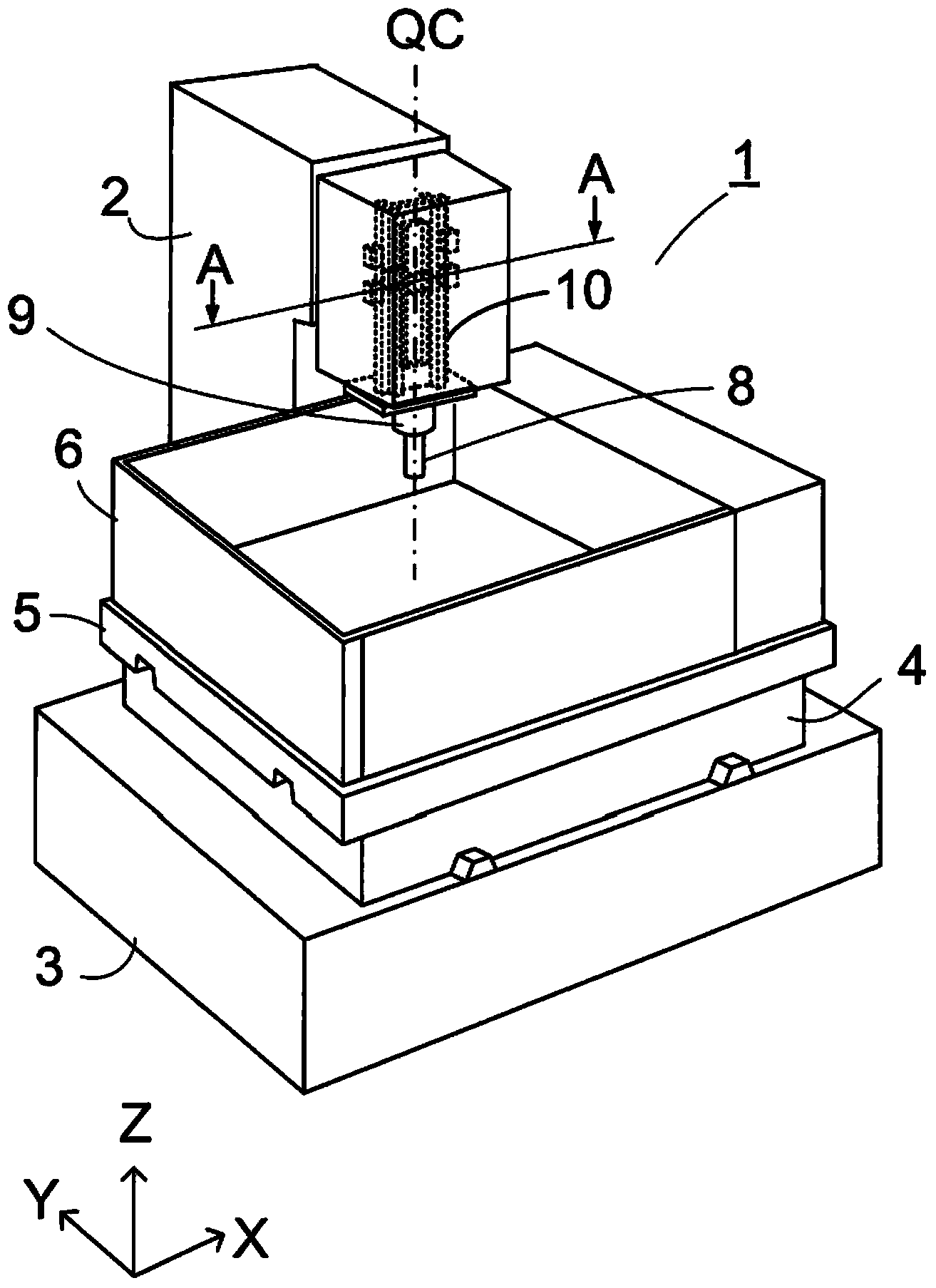
[0056] Below, refer to Figure 1 to Figure 4 The electrical discharge machining device of the present invention will be described. Such as figure 1 As shown, a column (column) 2 is disposed behind a machine bed 3 , and a seat plate (saddle) 4 is provided on the machine bed 3 so as to be slidable along the Y-axis direction. A platform (table) 5 is slidably disposed on the seat plate 4 along the X-axis direction. A processing tank 6 is provided on the platform 5 , and a workpiece (not shown) is fixed in the processing tank 6 . Machining tank 6 is filled with EDM fluid during machining.

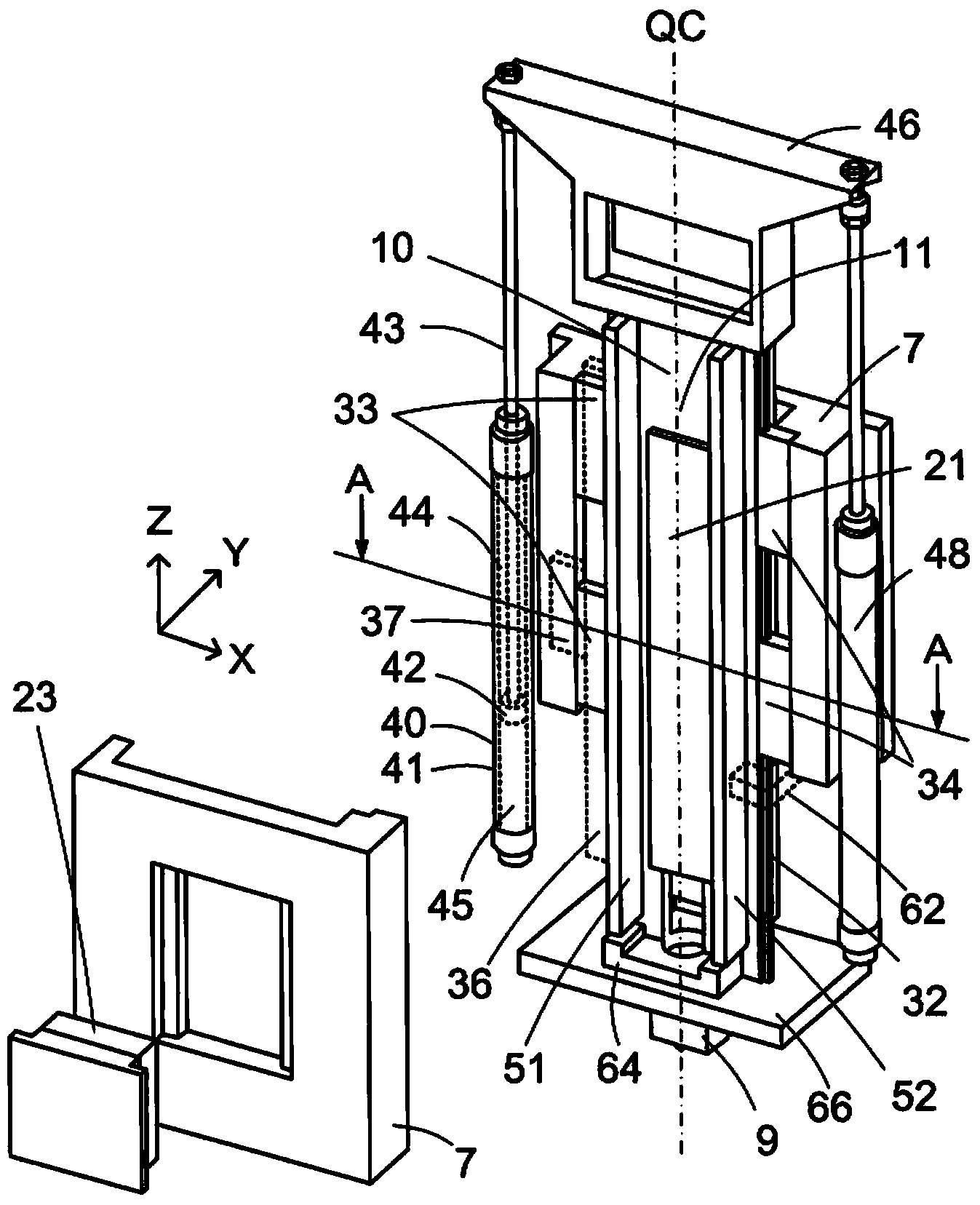
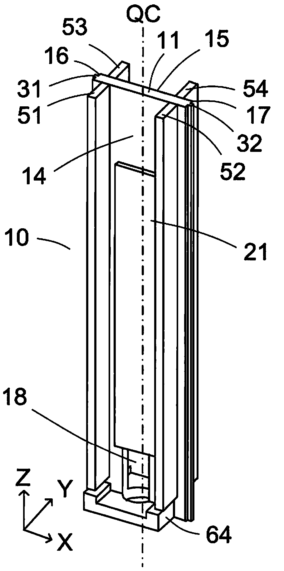
[0057] The holding member 7 is fixed to the front of the column 2 . The holding member 7 has a hole through which the main shaft 10 passes vertically. The spindle 10 is held by the holding member 7 so as to be movable in the Z-axis direction. The tool electrode 8 may be directly or indirectly attached to the lower end of the main shaft 10 . In the embodiment, the tool electrode 8 is insta...


PUM


Abstract

A sinker electric discharge machining apparatus includes a quill 10, to which a tool electrode is attached, and a linear motor device configured to generate a linear movement of the quill towards a workpiece. The quill includes a plate member 11 made of a metal or an alloy, a first reinforcing member 51 fixed to a front surface 14 of the plate member, a second reinforcing member 52 fixed to the front surface of the plate member, a third reinforcing member 53 fixed to a back surface 15 of the plate member and disposed opposite to the first reinforcing member across the plate member, and a fourth reinforcing member 54 fixed to the back surface of the plate member and disposed opposite to the second reinforcing member across the plate member. The quill has a cross-section that is symmetric in a width direction of the plate member.

Description

technical field [0001] The present invention relates to an electric discharge machining device which generates electric discharge in a work gap formed between a conductive workpiece and a tool electrode to process the workpiece. More particularly, the present invention relates to a sinker electric discharge machining apparatus for advancing a tool electrode mounted in a spindle towards a workpiece. Background technique [0002] Electric discharge forming apparatuses are widely used to precisely manufacture molds. Generally, the tool electrode is mounted on a vertically movable quill or ram using a tool holder. Tool electrodes are usually made of copper or graphite. The workpiece is fixed on a work table arranged in a work tank. During machining, the machining tank is filled with a dielectric liquid and the tool electrode is positioned very close to the workpiece. The size of the processing gap is about several microns to hundreds of microns. [0003] When a power pulse ...

Claims


Application Information

Patent Timeline
Patent Type & Authority Applications(China)
IPC IPC(8): B23H1/00B23H11/00
CPCB23H7/265B23H1/00B23H7/30
Inventor 冈崎秀二保坂昭夫
Owner SODICK CO LTD
Why Eureka
Try Eureka