
For orthopaedic surgery V-type double flat support lower extremity traction device

An orthopaedic surgery and traction device technology, applied in surgery, operating table, medical science and other directions, can solve the problems of cumbersome traction operation, secondary injury to patients, affecting accurate positioning, etc., to expand the scope of treatment, save space, and reduce traction stable effect

Inactive Publication Date: 2016-05-11
SECOND AFFILIATED HOSPITAL OF XIAN MEDICAL UNIV
View PDF7 Cites 0 Cited by
  • Summary
  • Abstract
  • Description
  • Claims
  • Application Information

AI Technical Summary

Problems solved by technology

The currently commonly used WX-S1380Q orthopedic traction frame is a lower limb traction device with a V-shaped double brace structure. The wheels under the rectangular base at the top of the V double brace are exposed, and the wheels under the open end of the V double brace are also exposed. The frame lacks stability and therefore often affects traction on the patient
In addition, this lower limb traction device also has a disadvantage that the central column on the rectangular base directly blocks the activity space of the "C"-shaped arm that moves the X-ray machine during the operation, thereby affecting the doctor's accurate positioning of the patient's injured part, and then directly Delay the best treatment effect for the patient
In addition, this lower limb traction device does not have a suitable auxiliary traction mechanism on the foot support that fixes the patient's feet, so the traction operation is not only cumbersome, but also the traction force cannot be accurately controlled, which may cause secondary injury to the patient at any time

Method used


Image

  • For orthopaedic surgery V-type double flat support lower extremity traction device

Examples


Embodiment Construction

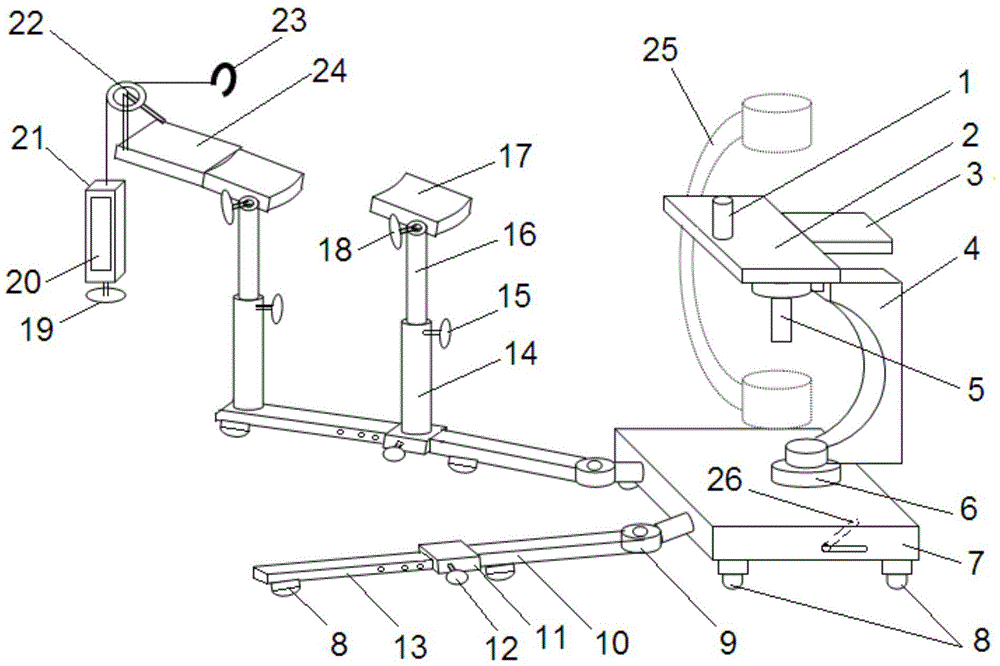
[0012] refer to figure 1 , a V-shaped double-planar lower limb traction device for orthopedic surgery, comprising a rectangular base 7, on the base connected to the concave arc vertical arm 4 through a turntable 6 (built-in flat bearing), the turntable 6 can make the concave arc vertical The arm rotates 360° in the horizontal direction, so as to avoid interference with C-arms 25 (see-through devices) of different sizes. The upper end of the concave arc vertical arm is connected to the seat plate 2 through the cooperation of the nut and the suspension screw 5, so as to be used as a support point for the buttocks when the patient is treated conveniently; Row. The rear side of the seat plate (the side close to the upper end of the concave arc vertical arm) is connected with a butt plate 3, which is used to combine with various types of operating beds. The combination of the suspension screw 5 and the nut can be used to adjust the height of the seat board to match the docking of...


PUM


Abstract

The invention discloses a V-shaped double-horizontal brace lower limb traction device for an orthopedic operation. The device comprises a base plate and a base, wherein a pair of V-shaped bottom horizontal braces is movably hinged to the front side of the base; two height-adjustable upright braces are arranged on each bottom horizontal brace, one upright brace is arranged the middle rear part of the bottom horizontal brace to support and fix the lower hip part of a patient, and the other upright brace is arranged at the front end of the bottom horizontal brace to support and fix the corresponding foot of the patient. The device is characterized in that an inwards-sunken arched vertical arm capable of horizontally rotating 360 degrees is connected to the base, wherein the upper end of the inwards-sunken arched vertical arm is connected with the base plate through a lifting mechanism; foot support flat plates are arranged on the upright braces for supporting and fixing the feet of the patients; a pulley is arranged on the front side of each foot support flat plate; a hook is connected to the end, on which a rope is wound, of each pulley to hook a foot strap of the patient; perpendicularly downward tractors are connected to the other ends of the rope, and apply traction force to the lower limbs of the patient through the pulleys and the ropes under the action of gravity.

Description

technical field [0001] The invention relates to a lower limb traction device for orthopedic surgery. Background technique [0002] In the orthopedic surgery performed on the patient's limbs, it is necessary to carry out lateral and horizontal traction and adduction and adduction positions on the patient's limbs. There must be a set of orthopedic surgery lower limb traction devices that can be used in combination with various types of operating beds. The currently commonly used WX-S1380Q orthopedic traction frame is a lower limb traction device with a V-shaped double brace structure. The wheels under the rectangular base at the top of the V double brace are exposed, and the wheels under the open end of the V double brace are also exposed. The frame lacks stability and, therefore, often affects the traction effect on the patient. In addition, this lower limb traction device also has a disadvantage that the central column on the rectangular base directly blocks the activity sp...

Claims


Application Information

Patent Timeline
Patent Type & Authority Patents(China)
IPC IPC(8): A61G13/12A61G13/00
Inventor 张兵王建榜张美张允东于军赵海康张林朱鹏李博鲍亮康晋张学策李军李安娜李四光吕宏学
Owner SECOND AFFILIATED HOSPITAL OF XIAN MEDICAL UNIV
Learn More