Eureka AIR delivers breakthrough ideas for toughest innovation challenges, trusted by R&D personnel around the world.

Seedbed heating system for planting greenhouse

A heating system and greenhouse technology, applied in the field of greenhouse seedbed heating system, can solve the problems of high content of smoke and carbon dioxide waste gas, uneven heating temperature, etc.

Inactive Publication Date: 2014-12-24
云南省玉溪市佳利太阳能设备有限公司 +1
View PDF6 Cites 8 Cited by
  • Summary
  • Abstract
  • Description
  • Claims
  • Application Information

AI Technical Summary

Problems solved by technology

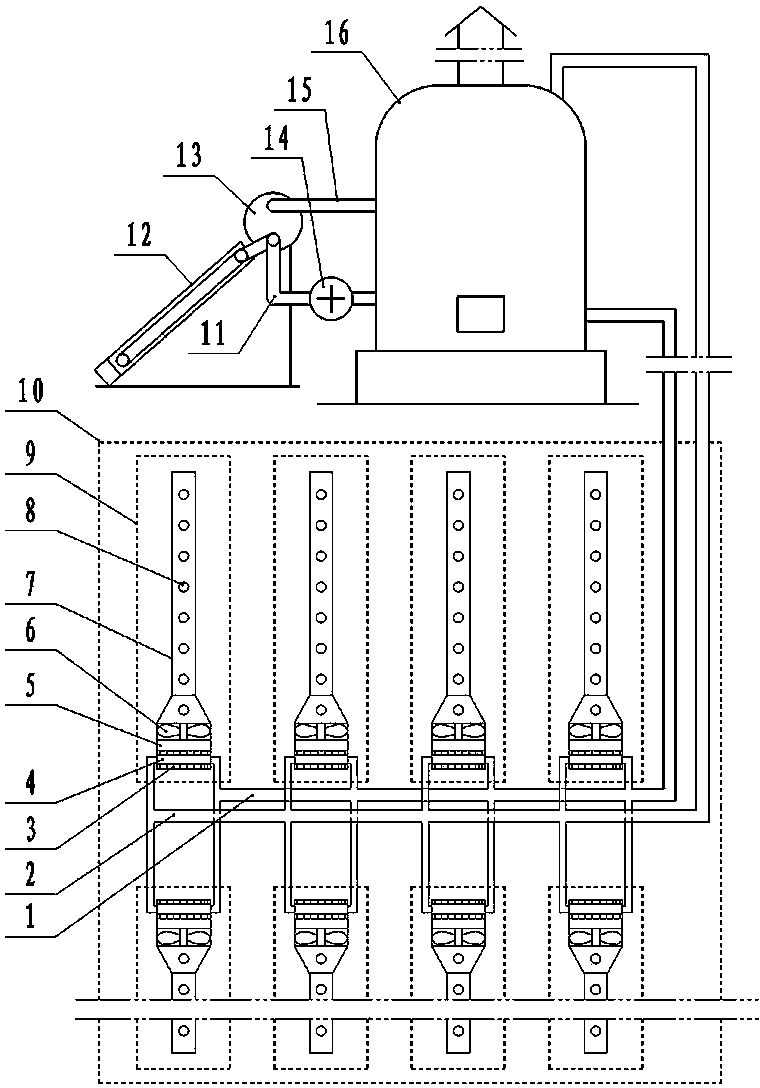
[0003] In view of the prior art, in the greenhouse planting in the south, a small hot air fan is used to heat the greenhouse, and there are problems such as uneven heating temperature in the greenhouse, high content of smoke and carbon dioxide waste gas, the present invention provides a greenhouse seedbed heating system, The system builds multiple sets of seedbeds higher than the ground in the greenhouse, and a coil radiator is installed under each seedbed in the greenhouse. Radiators are installed on the radiators, and the radiators and hot steam outlet pipes and The inlet pipe of the cold water is connected to the front end of the radiator with an air duct, the front end of the air duct is equipped with an exhaust fan, the front end of the exhaust fan is equipped with an air supply pipe, the front end of the air supply pipe is closed, and the upper end has a hot air outlet hole, The steam outlet pipe and the cold water inlet pipe are connected to the water chamber of the heating boiler outside the greenhouse; a group of solar water heaters are installed next to the heating boiler, and the water inlet pipe and outlet pipe on the water storage tank of the solar water heater are respectively connected to the water chamber of the boiler. Inside, an auxiliary circulation pump is installed on the outlet pipe of the solar water heater storage tank

Method used


Image

  • Seedbed heating system for planting greenhouse

Examples


Embodiment

[0006] Example: such as figure 1 As shown, a planting greenhouse seedbed heating system has multiple groups of seedbeds 9 higher than the ground built in the planting greenhouse 10, and is characterized in that: a coil radiator 4 is installed under each seedbed 9 in the greenhouse, Radiator 4 is provided with heat sink 3, and radiator 4 is connected with outlet pipe 2 of hot steam and inlet pipe 1 of cold water. At the front end of radiator 4, air duct 5 is installed, and an exhaust fan is installed at the front end of air duct 5. 6. The front end of the exhaust fan 6 is equipped with an air supply pipe 7, the front end of the air supply pipe 7 is closed, and the upper end is opened with a hot air outlet 8. The outlet pipe 2 of hot steam and the inlet pipe 1 of cold water are connected to the heating boiler 16 outside the greenhouse In the water cavity of heating boiler 16, a group of solar water heaters 12 are installed, and the water inlet pipe 15 and the water outlet pipe 1...


PUM


Abstract

The invention discloses a seedbed heating system for a planting greenhouse. The seedbed heating system is characterized in that a heat radiator is arranged below each seedbed in the planting greenhouse and is connected with an exhaust pipe of hot steam and a feeding pipe of cold water; an exhaust fan is arranged at the front end of each heat radiator; an air supply duct is arranged at the front end of the corresponding exhaust fan; hot air outlet holes are formed in the upper end of each air supply duct; the exhaust pipe of the hot steam and the feeding pipe of the cold water are connected to the inside of a water cavity of a heating boiler outside the greenhouse; a group of solar auxiliary water heaters is arranged beside the heating boiler. The hot stem is circularly heated in the greenhouse, so that smoke dust and carbon dioxide waste gas in the greenhouse are avoided; a solar water heating device is arranged on the boiler outside the greenhouse in an assisting manner, so that the consumption of fuel of the boiler is greatly reduced; the heat radiators, the exhaust fans and the air supply ducts are respectively used for heating on the seedbeds, so the planting temperatures of plants planted on the seedbeds are basically consistent, and the utilization of heat is more reasonable.

Description

technical field [0001] The invention belongs to the technical field of heating facilities used in planting sheds in agricultural production, and relates to a planting shed seedbed heating system. Background technique [0002] Greenhouse planting is a technology widely used in agricultural production. In winter, many plants need to be heated in the shed when they enter the greenhouse area, especially in the planting of flowers. Using heating technology for planting and production of winter flowers is a widely used technology. In the north of our country, the structure of the greenhouse for flower planting is complex, and the winter heating system and summer cooling system installed in it are complex in structure and high in energy consumption; As a result, the heating temperature in the shed is uneven, the growth of the planted plants varies greatly, and the high content of smoke and carbon dioxide in the shed affects the growth of plants and the service life of the shed. ...

Claims


Application Information

Patent Timeline
IPC IPC(8): A01G9/24
CPCY02A40/25Y02P60/12
Inventor 雷佳雷兴龙普艳红
Owner 云南省玉溪市佳利太阳能设备有限公司
Why Eureka
Eureka Blog
Learn More