
Piston for an internal combustion engine

A technology for internal combustion engines and pistons, applied to pistons, mechanical equipment, engine components, etc., can solve problems such as damage to piston rings

Inactive Publication Date: 2014-12-17
MAHLE INT GMBH
View PDF8 Cites 4 Cited by
  • Summary
  • Abstract
  • Description
  • Claims
  • Application Information

AI Technical Summary

Problems solved by technology

This oil carbon layer will in turn function as an insulator and will contribute to the excessive heating of the piston ring, thus destroying the piston ring

Method used


Image

  • Piston for an internal combustion engine
  • Piston for an internal combustion engine
  • Piston for an internal combustion engine

Examples


Embodiment Construction

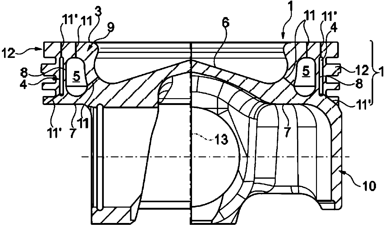
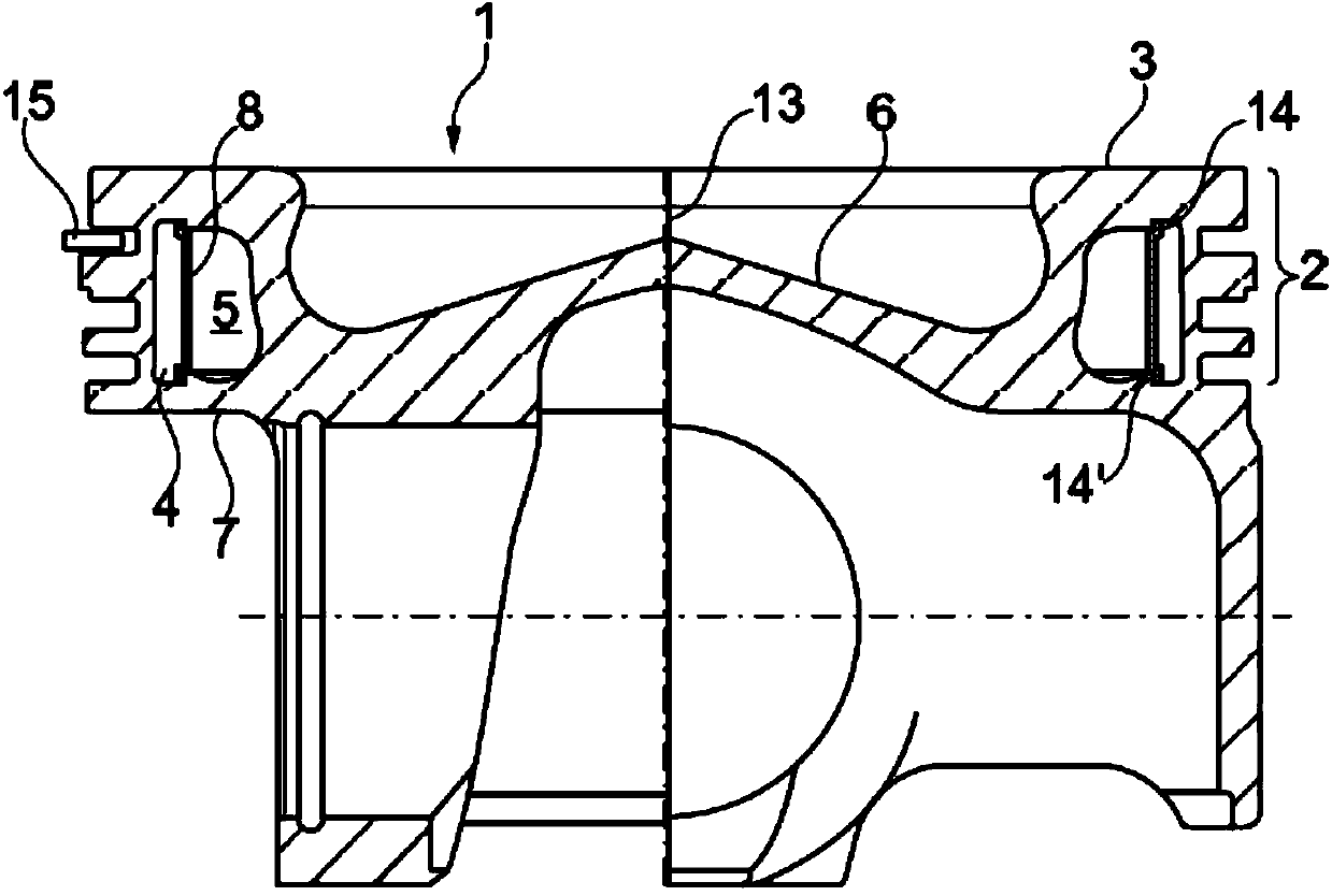
[0025] according to Figures 1 to 4 , according to the invention a piston 1 for an internal combustion engine (not shown) has: a surrounding ring segment 2 in the region of the piston crown 3; a surrounding outer channel 4 in the region of the ring segment 2; and arranged coaxially therewith The inner channel 5. According to the invention, the outer channel 4 is now designed as a thermal insulator, which accordingly insulates the ring segment 2 from the inner channel 5 and the piston bowl 6, which is also designated as the combustion chamber bowl, while the inner channel 5 is designed as a cooling channel and contains The heat transfer medium serves to dissipate heat from the piston crown 3 to the piston underside 7 of the piston 1 .

[0026] The outer channel 4 and the inner channel 5 are here separated from one another by a partition wall 8, wherein the partition wall can be constructed as a separate structural part, in particular as Figures 2 to 4 Illustrated, or wherein...


PUM


Abstract

The present invention relates to a piston (1) for an internal combustion engine, having an encircling ring section (2) in the region of a piston crown (3), having a convection region with a cavity containing a cooling fluid, for example an encircling inner duct (5), and having a heat insulation region arranged between the ring section (2) and the convection region, the heat insulation region being for example an encircling outer duct (4) arranged coaxially with respect to said ring section and convection region. Here, it is essential to the invention that the outer duct (4) is in the form of a heat insulator which reduces a heat flow substantially radially outward and which thermally insulates the ring section (2) with respect to the high temperatures at the piston crown and the inner duct (5), whereas the inner duct (5) is in the form of a cooling duct and contains a heat transfer medium for the improved dissipation of heat from a piston crown to the underside (7) of the piston (1) by convection.

Description

technical field [0001] The invention relates to a piston for an internal combustion engine, according to the preamble of claim 1 , having a circumferential ring segment in the area of ​​the piston crown, a convection area and a thermal insulation area arranged between the ring segment and the convection area. Background technique [0002] From DE 10 2004 038 464 A1 a universal piston is known, in particular a cooling channel piston for an internal combustion engine, which has an upper part and a lower part which can be produced separately from each other and subsequently joined together, wherein the upper part has at least three diameters As for the wrap-around joining spokes, the lower part likewise has at least three radially wrap-around joining spokes, which are joined together during the joining process, via which spokes the upper part is reliably connected to the lower part. [0003] From DE 10028926 A1 a composite piston is known which has a piston crown made of a high...

Claims


Application Information

Patent Timeline
IPC IPC(8): F02F3/18
CPCF02F3/18F02F3/20
Inventor 萨沙-奥利弗·布泽克
Owner MAHLE INT GMBH
Learn More