
Electrolytic capacitor for quick charging system of new energy vehicle

A technology for electrolytic capacitors and new energy vehicles, applied in the field of capacitors, can solve the problem of weak shock resistance, and achieve the effect of improving the withstand voltage, current shock resistance, and increasing the number of

Inactive Publication Date: 2014-12-17
ZHAOQING BERYL ELECTRONICS TECH
View PDF4 Cites 3 Cited by
  • Summary
  • Abstract
  • Description
  • Claims
  • Application Information

AI Technical Summary

Problems solved by technology

[0005] Currently, it usually takes 8-10 hours to charge new energy vehicles. In order to achieve fast charging, the surge charging method is generally used. This method can shorten the time by 2-4 hours, and the above method requires the capacitor to withstand 4.7A. The above current, but the existing liquid capacitors can only withstand the current of 3A, and the impact resistance is not strong. Therefore, an electrolytic capacitor is needed, which can meet the requirements of fast charging of new energy vehicles.

Method used


Image

  • Electrolytic capacitor for quick charging system of new energy vehicle
  • Electrolytic capacitor for quick charging system of new energy vehicle

Examples


Embodiment Construction

[0023] The accompanying drawings are for illustrative purposes only, and should not be construed as limitations on this patent; in order to better illustrate this embodiment, certain components in the accompanying drawings will be omitted, enlarged or reduced, and do not represent the size of the actual product; for those skilled in the art It is understandable that some well-known structures and descriptions thereof may be omitted in the drawings. The positional relationship described in the drawings is for illustrative purposes only, and should not be construed as a limitation on this patent.

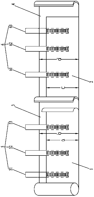
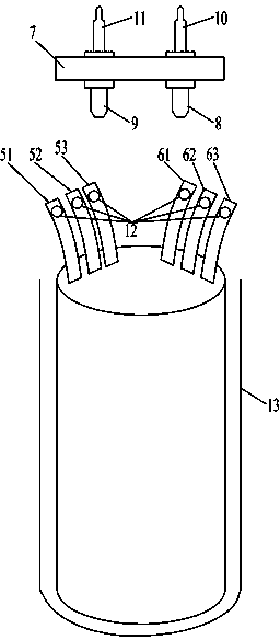
[0024] like figure 1 , 2 As shown, an electrolytic capacitor for a fast charging system of a new energy vehicle includes an aluminum shell 13, an anode aluminum foil 1, a cathode aluminum foil 2, a first electrolytic paper 3, a second electrolytic paper 4, an anode lead 5, a cathode lead 6, a capacitor Cover 7;

[0025] The anode lead wire 5 is riveted on the anode aluminum foil 1,...


PUM


Abstract

The invention relates to the technical field of capacitors, in particular to an electrolytic capacitor for a quick charging system of a new energy vehicle. The electrolytic capacitor for the quick charging system of the new energy vehicle is characterized in that at least three anode leads are riveted to an anode aluminum foil, at least three cathode leads are riveted to a cathode aluminum foil, the electrolytic capacitor comprises an anode aluminum foil, first electrolytic paper, a cathode aluminum foil and second electrolytic paper from the inside to the outside, and the anode aluminum foil, the first electrolytic paper, the cathode aluminum foil and the second electrolytic paper are wound to form an element which is sleeved with a capacitor cover and placed in an aluminum shell. The electrolytic capacitor has the advantages that due to increase of lead quantity, contact areas of the leads and the aluminum foils are widened, impedance is reduced, and current surge resistance is improved; by size arrangement, withstand voltage of the electrolytic capacitor is increased while specific volume and internal resistance are reduced; voltage endurance capability can be improved owing to high-density composite paper, and more electrolyte can be absorbed by low-density composite paper, so that service life of the whole electrolytic capacitor can be prolonged.

Description

technical field [0001] The present invention relates to the technical field of capacitors, and more specifically, relates to an electrolytic capacitor for a fast charging system of a new energy vehicle. Background technique [0002] Electrolytic capacitor is a kind of capacitor, the metal foil is the positive electrode (aluminum or tantalum), the oxide film (aluminum oxide or tantalum pentoxide) close to the metal is the dielectric, the cathode is made of conductive material, electrolyte (the electrolyte can be liquid or Solid) and other materials, because the electrolyte is the main part of the cathode, so the name of the electrolytic capacitor. At the same time, the positive and negative of the electrolytic capacitor cannot be connected incorrectly. [0003] Features of electrolytic capacitors 1: The capacitance per unit volume is very large, dozens to hundreds of times larger than other types of capacitance. The second characteristic of electrolytic capacitors: the rat...

Claims


Application Information

Patent Timeline
Patent Type & Authority Applications(China)
IPC IPC(8): H01G9/008H01G9/07H01G9/04
Inventor 刘泳澎罗伟廖琼成旭
Owner ZHAOQING BERYL ELECTRONICS TECH
Learn More