Transformer respirator

A respirator and transformer technology, applied in the direction of transformer/inductor cooling, etc., can solve the problems of affecting the sealing effect, poor sealing, freezing and cracking of oil marks, etc., to achieve the effect of convenient operation and increased height

Inactive Publication Date: 2014-12-17
STATE GRID CORP OF CHINA +1
View PDF7 Cites 3 Cited by
  • Summary
  • Abstract
  • Description
  • Claims
  • Application Information

AI Technical Summary

Problems solved by technology

The transformer respirator with this structure has the following problems: 1. Since there is only one silica gel injection and discharge port, when the silica gel deliquescence needs to be replaced, the oil cup must be removed first, and then the flange connection bolts on the top of the silica gel tank must be removed. Then turn the silica gel tank upside down so that the silica gel is discharged from the silica gel injection outlet, and the operation is cumbersome; 2. Since the sealing ring is opened during the disassembly process, the sealing effect will be affected when it is reinstalled, and it is easy to leak; 3. The long bolt is inserted into the silica gel tank. Pass through, the gasket set at the connection between it and the end cover, the seal here is not good, it is easy to cause air leakage
4. Snow water in winter is easy to flow into the oil cup from the outer wall of the silicone tank along the bottom surface of the lower end cover, and it is easy to crack the oil standard after freezing

Method used


Image

  • Transformer respirator

Examples


Embodiment Construction

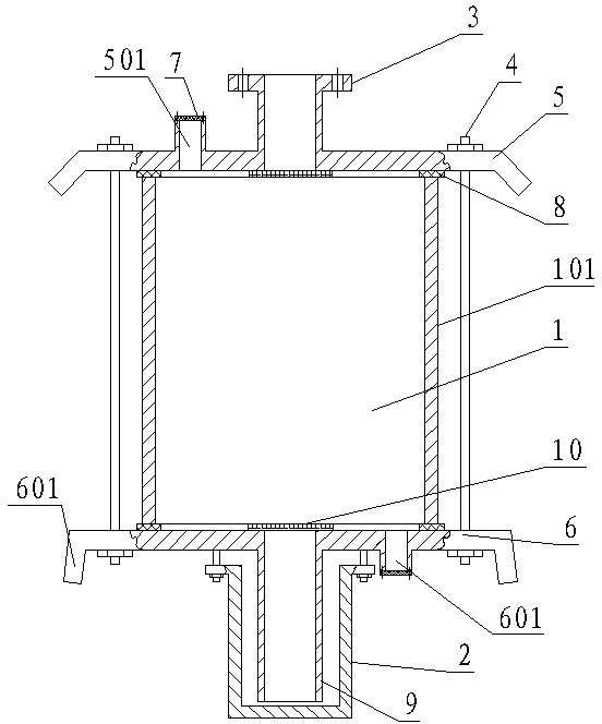
[0013] As shown in the figure, the transformer respirator includes a silica gel tank 1, an oil cup 2 located at the bottom center of the silica gel tank 1, and a flange 3 located at the top center of the silica gel tank 1; the silica gel tank 1 is made of a glass tank body 101 1. The upper and lower end caps 5, 6 connected to the port of the glass tank body 101 by long bolts 4 are formed by a sealing ring 8 arranged between the silica gel tank 1 and the upper and lower end caps; the bottom exhaust pipe 9 of the silica gel tank 1 Insert it into the oil cup 2 and keep a distance of 1cm-2cm from the inner bottom surface of the oil cup 2. On the upper and lower end covers 5 and 6, respectively set a silicone injection port 501 and a silica gel discharge port 601. The sealing cover 10, the long bolt 4 is located outside the silicone tank 1, the outer edge of the lower end cover 6 is provided with a water retaining edge 602 extending downward, and the height of the oil cup 2 is 80mm-...


PUM

PropertyMeasurementUnit
heightaaaaaaaaaa
heightaaaaaaaaaa

Abstract

The invention relates to a transformer respirator, which comprises a silica gel tank, an oil cup and a flange, wherein the flange is arranged in the center of the top of the silica gel tank, the silica gel tank consists of a glass tank body, an upper end cover, a lower end cover, long screw bolts and sealing rings, the upper end cover and the lower end cover are connected onto an end opening of the glass tank body through screw bolts, the long screw bolts are connected between the upper end cover and the lower end cover, the sealing rings are arranged between the tank body and the upper and lower end covers, and an exhaust pipe arranged at the bottom of the lower end cover is inserted in the oil cup. The transformer respirator is characterized in that a silica gel filling opening and a silica gel discharging opening are respectively formed in the upper end cover and the lower end cover, sealing covers are arranged on the silica gel filling opening and the silica gel discharging opening, the long screw bolts are positioned outside the glass tank body, the outer edge of the lower end cover is provided with a downwards extending water blocking edge, and the height of the oil cup is 80mm to 100mm. The operation is convenient, and the original sealing structure cannot be destroyed; the problem of air leakage caused by poor sealing between the long screw bolts and the tank body since the long screw bolts are positioned in the tank body is solved; snow water in winter is prevented from flowing into the oil cup from the outer wall of the silica gel tank along the bottom surface of the lower end cover; the loss of aqueous vapor absorption effect due to oil film forming through the contact of oil and silica gel particles is prevented.

Description

technical field [0001] The invention relates to a transformer respirator. Background technique [0002] As the main equipment in the power system, the safe and stable operation of the transformer directly affects the reliability of the power supply. As a part of the transformer, the respirator is generally composed of a silicone tank, an oil cup at the bottom center of the silicone tank, and a method at the top center of the silicone tank. Orchid composition. The silicone tube is composed of a glass tank body, the upper and lower end caps connected to the port of the glass tank body by bolts, the long bolts connected between the upper and lower end caps and passing through the tank body, and arranged between the glass tank body and the end caps. It consists of a sealing ring between the long bolts and the end cover; the upper end cover is provided with a silica gel injection and discharge port. The transformer respirator with this structure has the following problems: 1. S...

Claims


Application Information

Patent Timeline
Patent Type & Authority Applications(China)
IPC IPC(8): H01F27/14
Inventor 夏金标周大宇马爱东冯佳川郭立东刘征陈哲汤德智刘春淼
Owner STATE GRID CORP OF CHINA
Why Eureka
Try Eureka