
Novel automobile beam forming process and stamping die structure

A stamping die and forming process technology, applied in the field of new automobile beam forming process and stamping die structure, can solve the problems of increased instability of parts, relatively high requirements, and many equipment utilization, saving equipment, shortening adjustment time, The effect of reducing waste

Inactive Publication Date: 2014-12-17
SAIC-GM-WULING AUTOMOBILE CO LTD
View PDF5 Cites 14 Cited by
  • Summary
  • Abstract
  • Description
  • Claims
  • Application Information

AI Technical Summary

Problems solved by technology

In the molding process of this kind of process scheme, because the mold does not adopt the part pressing and fixing mechanism, the material is not pressed and fixed, the material can flow immediately, the material is not controlled during the molding process, and wrinkling defects are easily formed; in the shaping process, Since the material is plastically deformed for the first time in the molding process, the yield and stress of the first plastic deformation must be overcome in the shaping process, so the material after shaping will have quality defects such as springback of the corresponding part, and the side wall of the shaped part The springback is uncontrolled; the requirements for the press are relatively high. If the equipment conditions change, the instability of the parts will increase, and waste products will easily be produced; the front frame and the rear frame of the car are each produced by a production line, sharing 6 presses for production , using a lot of equipment and low production efficiency

Method used


Image

  • Novel automobile beam forming process and stamping die structure
  • Novel automobile beam forming process and stamping die structure
  • Novel automobile beam forming process and stamping die structure

Examples


Embodiment Construction

[0062] The present invention will be further described below in conjunction with the drawings.

[0063] The structure of the stamping die of the present invention will be described in detail below with reference to the accompanying drawings.

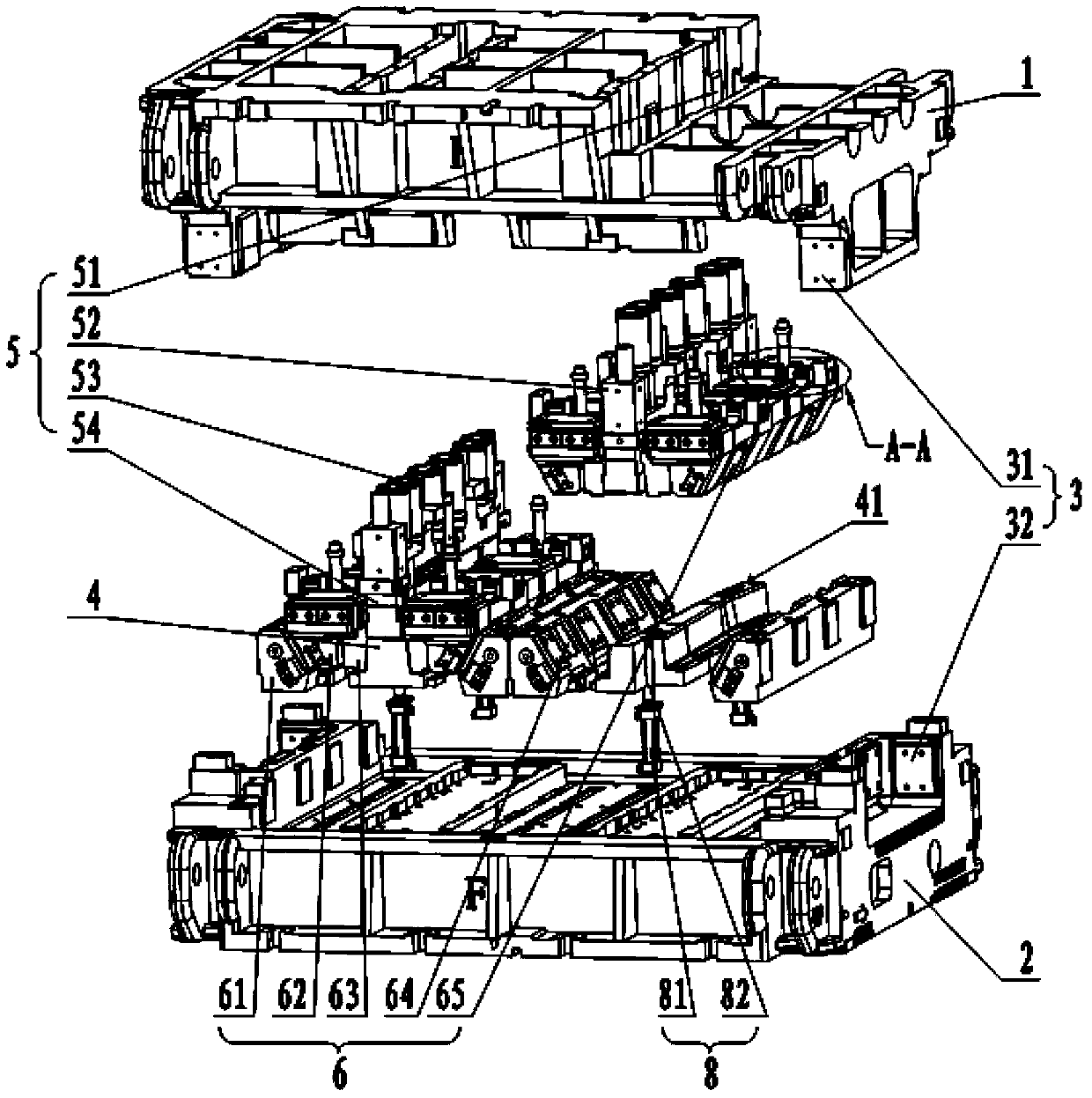
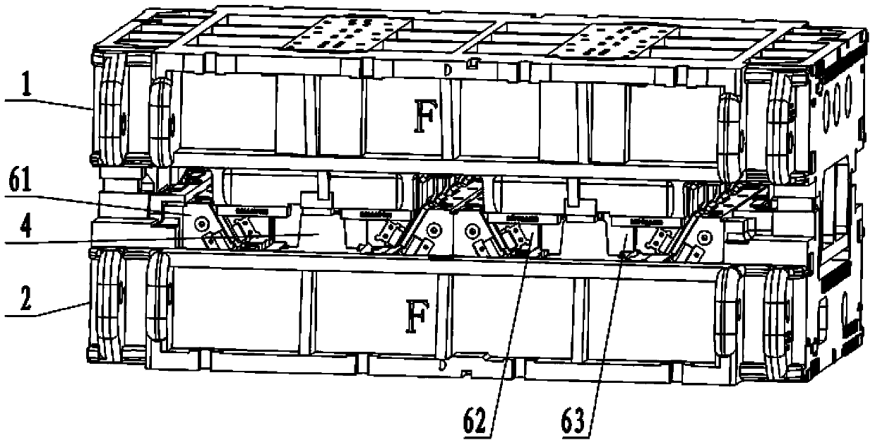
[0064] As shown in Figure 1, Figure 2 and Figure 3, the stamping die structure includes an upper mold base 1, a lower mold base 2, and a mold base guide mechanism 3 respectively connected to the upper mold base 1 and the lower mold base 2 , The pressing core 4 used to place the workpiece, the stripping mechanism 8 connected to the pressing core 4 and the lower mold base 2 respectively, the pressing mechanism 5 connected to the upper mold base 1, and the upper The molding / side shaping mechanism 6 connected to the mold base 1 and the lower mold base 2 respectively, the material pressing core 4 is fixed to the lower mold base 2; the material pressing core 4 is placed on the molding material of the required size of the automobile beam, The upper...


PUM


Abstract

The invention provides a novel automobile beam forming process and a stamping die structure. The stamping die structure comprises a material pressing core, a material pressing mechanism and a forming and side shaping mechanism. When the stamping die structure works, a workpiece is placed on the material pressing core, the material pressing mechanism makes contact with the workpiece firstly and then presses and fixes the workpiece, and then the forming and side shaping mechanism begins to make contact with the workpiece and works. The forming process includes a blanking procedure, a forming and side shaping procedure and a hole stamping and edge trimming procedure, wherein in the forming and side shaping procedure, wrinkling, cracking, unstability and surface quality of the workpiece are debugged, all profiles are shaped, and resilience of the side wall of the workpiece is controlled; in the hole stamping and edge trimming procedure, hole stamping and edge trimming are carried out on the workpiece. According to the stamping die structure, wrinkles of parts are reduced, resilience of the parts is effectively controlled, beam forming parts do not excessively rely on production equipment any longer, and the production mode that two workpieces can be produced through one die is achieved. By means of the process, an automobile beam can be formed through the three procedures, and production efficiency is improved. The process and the stamping die structure are suitable for production of the automobile beam parts.

Description

technical field [0001] The invention relates to a stamping process and a die structure, in particular to a novel automobile beam forming process and a stamping die structure. Background technique [0002] For the beam parts of automobiles, they can generally be divided into two types: one is relatively complex in structure, and there is a drop in the width and height directions; the other is relatively simple in structure, and there is basically no drop in the width and height directions. Straight beams, such as the front frame of the car and the rear frame of the car. For the second type of automobile girder, the process plan we generally adopt is: blanking (sheet material)-forming-shaping-punching, a total of four processes are completed. This process scheme is a relatively common technical scheme for many years. In the molding process of this kind of process scheme, because the mold does not adopt the part pressing and fixing mechanism, the material is not pressed and f...

Claims


Application Information

Patent Timeline
IPC IPC(8): B21D37/10B21D35/00B21D53/88
Inventor 陈伊娜乔晓勇苏飞宇
Owner SAIC-GM-WULING AUTOMOBILE CO LTD
Learn More