Catalyst packing device of bubble tower-type slurry bed reactor and catalyst packing method of bubble tower-type slurry bed reactor

A filling device and filling method technology, applied in chemical instruments and methods, organic chemistry, hydrocarbons, etc., can solve problems such as clogging of pipes or valves, and achieve the effect of avoiding mechanical loss

Inactive Publication Date: 2014-12-10
JAPAN OIL GAS & METALS NAT CORP +5
View PDF10 Cites 1 Cited by
  • Summary
  • Abstract
  • Description
  • Claims
  • Application Information

AI Technical Summary

Problems solved by technology

Therefore, the inventors paid attention to the following problem: Even if the slurry prepared by the catalyst is put into the reactor while taking out the catalyst in the reactor, the catalyst will be precipitated and separated from the slurry during the operation, so that the piping Or blockage will occur near the valve

Method used


Image

  • Catalyst packing device of bubble tower-type slurry bed reactor and catalyst packing method of bubble tower-type slurry bed reactor
  • Catalyst packing device of bubble tower-type slurry bed reactor and catalyst packing method of bubble tower-type slurry bed reactor
  • Catalyst packing device of bubble tower-type slurry bed reactor and catalyst packing method of bubble tower-type slurry bed reactor

Examples


Embodiment Construction

[0043] Next, the catalyst filling device for the bubble column slurry bed reactor and the catalyst filling method for the bubble column slurry bed reactor of the present invention will be described in detail.

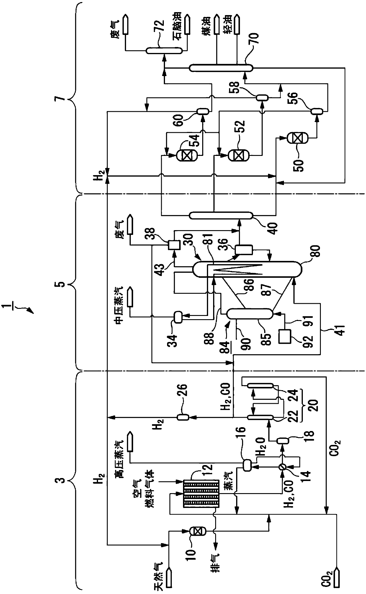
[0044] First, refer to figure 1 A liquid fuel synthesis system including a bubble column type slurry bed reactor according to the present invention will be described.

[0045] figure 1 The liquid fuel synthesis system 1 shown is a factory equipment for implementing the GTL process of converting hydrocarbon raw materials such as natural gas into liquid fuels.

[0046] The liquid fuel synthesis system 1 is composed of a synthesis gas production unit 3 , an FT synthesis unit 5 , and a product refining unit 7 . The synthesis gas production unit 3 reforms natural gas which is a hydrocarbon raw material to produce synthesis gas containing carbon monoxide gas and hydrogen gas. The FT synthesis unit 5 synthesizes liquid hydrocarbons from the synthesis gas produced in the syn...


PUM


Abstract

Provided is a catalyst packing device disposed at a bubble tower-type slurry bed reactor for FT synthesis. The packing device comprises, disposed adjacent to the reactor, a slurry preparation cell for preparing a slurry S from an FT synthesis catalyst and a slurry preparation oil, a top communicating pipe for guiding slurry from the reactor to the slurry preparation cell and a bottom communicating pipe for guiding slurry from the slurry preparation cell to the reactor, and an equalizing pipe for communication between the inside of the reactor and the inside of the slurry preparation cell. The top communicating pipe is inclined down from the reactor toward the slurry preparation cell and the bottom communicating pipe is inclined up from the reactor toward the slurry preparation cell. Inert gas introduction means for introducing inert gas are disposed at the slurry preparation cell.

Description

technical field [0001] The invention relates to a catalyst filling device for a bubble column type slurry bed reactor and a catalyst filling method for the bubble column type slurry bed reactor. [0002] this application claims priority to the patent application 2012-074758 for which it applied to Japan on March 28, 2012, The content is used here. Background technique [0003] In recent years, from the viewpoint of reducing the environmental load, environmentally friendly green liquid fuels with low sulfur components and aromatic hydrocarbon contents have been sought. From this point of view, as a technology capable of producing fuel oil bases free of sulfur components, aromatic hydrocarbons, and rich in aliphatic hydrocarbons, especially kerosene and light oil bases, the use of carbon monoxide gas (CO) has been studied. and hydrogen (H 2 ) is a method of Fischer-Tropsch synthesis reaction (hereinafter referred to as "FT synthesis reaction") of raw material gas (for exampl...

Claims


Application Information

Patent Timeline
IPC IPC(8): C10G2/00B01J8/22
CPCB01J8/228B01J8/222B01J8/20B01J2208/00141B01J8/22C10G2/342B01J2208/0061B01J2219/00009C07C1/0415
Inventor 田坂和彦
Owner JAPAN OIL GAS & METALS NAT CORP
Why Eureka
Try Eureka