Spiral rotor and spiral expansion mechanism

A screw cone and rotor technology, applied in mechanical equipment, engine components, machines/engines, etc., can solve problems such as low energy utilization efficiency, and achieve the effect of avoiding thermal energy loss, preventing leakage, and improving thermal energy utilization efficiency.

Active Publication Date: 2016-08-17
北京发源动力机械设计研究有限公司
View PDF4 Cites 0 Cited by
  • Summary
  • Abstract
  • Description
  • Claims
  • Application Information

AI Technical Summary

Problems solved by technology

[0006] The present invention aims at the problem of low energy utilization efficiency in the prior art, uses a spiral cone rotor with a rotating spiral cone surface as the expansion mechanism, and utilizes its unique continuously variable volume change of the closed space to release heat energy of the high-temperature and high-pressure working medium. Spiral cone expansion mechanism that can improve heat energy utilization efficiency

Method used


Image

  • Spiral rotor and spiral expansion mechanism
  • Spiral rotor and spiral expansion mechanism
  • Spiral rotor and spiral expansion mechanism

Examples


Embodiment Construction

[0042] The present invention will be described below in conjunction with the accompanying drawings.

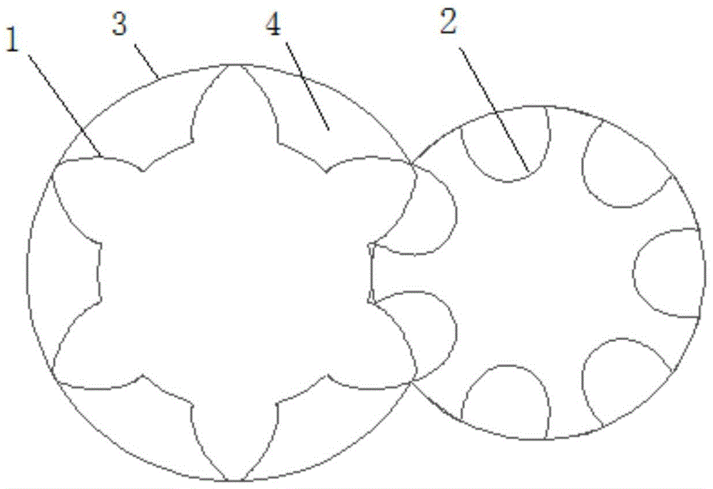
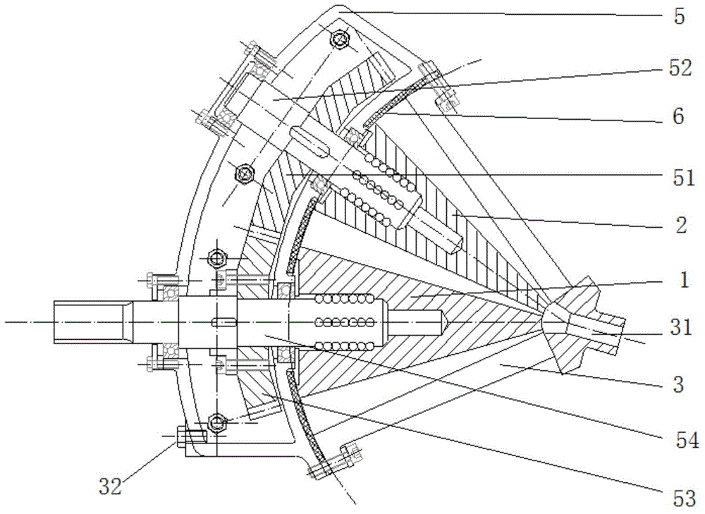
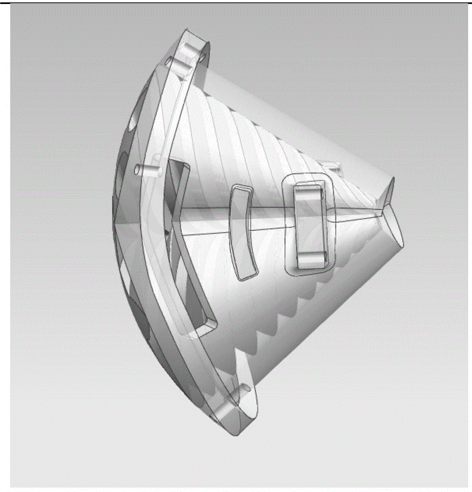
[0043] like figure 2 , image 3 As shown, the spiral cone rotor of the present invention includes a convex rotor 1 and a concave rotor 2 that rotate in opposite directions and have overlapping areas, and a casing 3 that wraps them together. The convex rotor 1 and the concave rotor 2 are screw-cone rotors with tapered profiles gradually converging along the axis of rotation, corresponding to them, such as Figure 4 The housing 3 shown has a double inner cone. The rotation axes of the convex rotor 1 and the concave rotor 2 intersect, and the angle between the two axes is 30°-60°. like Figure 5 As shown, the conical surface of the convex rotor 1 is provided with helically extended convex teeth 11 from the large end to the small end, and the concave rotor 2 is provided with grooves 21 in the same way, the curved surface of the convex teeth 11, the curved surface of the groov...


PUM


Abstract

The invention relates to a spiral cone rotor and a spiral cone expansion mechanism. The spiral cone rotor is on the basis of a plane conjugate curve which can form a continuous variable area; the curve extends to form a convex rotor with a three-dimensional space curved surface, a concave rotor with a three-dimensional space curved surface and an outer shell with double inner conical surfaces; spiral continuous, volume-variable and closed working space is generated by the opposite rotation between the convex rotor and the concave rotor. A high-pressure gaseous working medium enters the working space, pressure is released through volume expansion to push the convex rotor and the concave rotor to perform continuous opposite rotation; the internal energy of the working medium is converted into mechanical energy to do work. Compared with the prior art, the contacts among the convex rotor, the concave rotor and the outer shell are tight, the problem of leakage triangle is avoided; moreover, in the continuous opposite rotating process of the convex rotor and the concave rotor, the processes of gas inlet, expansion work and gas exhaust are completed by the high-pressure gaseous working medium continuously. The spiral cone rotor does not have an independent ventilation mechanism, so that the mechanical loss is minimized.

Description

technical field [0001] The invention relates to a volumetric fluid machine and a power machine, in particular to a mechanism for converting thermal energy into mechanical energy through a working space of varying volume. Background technique [0002] Traditional steam turbine thermal power conversion equipment uses high-pressure, high-temperature superheated steam to drive the steam turbine to convert it into shaft power, and then drives a synchronous generator to generate electricity, thereby realizing the conversion of heat energy to electrical energy. However, the steam turbine must consume high-grade heat sources such as superheated steam, which cannot be used Low grade heat source. At the same time, because the steam turbine produces a lot of exhaust steam during the heat power conversion process, the energy utilization efficiency is low. [0003] A gas turbine is a commonly used rotary power machine that converts a high-temperature gas working medium into mechanical w...

Claims


Application Information

Patent Timeline
Patent Type & Authority Patents(China)
IPC IPC(8): F01C21/08F01C1/16
Inventor 黄友钢
Owner 北京发源动力机械设计研究有限公司
Why Eureka
Try Eureka