


Quick Research
Generate reliable direction feasibility study reports for your R&D in just a few steps.

Technical Q&A
Discover and master advanced knowledge NOW. Basics, ideas, possibilities, all at once.

Find Solutions
As an expert in R&D theories, this can generate solutions to your technical problems instantly.

Evaluate Feasibility
Analyze your overall solution with one click, know your potential R&D risks in advance.

Monitor Landscape
Get weekly tech updates, stay abreast of the latest tech innovations and key insights.
Anti-bending bus IC card shell structure
A technology of intelligent bus card and shell structure, which is applied in the direction of recording carriers used in machines, instruments, computer components, etc. It can solve the problems of being bent, chip damage, and easy loss, etc., to slow down distortion and prevent chips from being damaged. loss, improve the effect of buffer protection
- Summary
- Abstract
- Description
- Claims
- Application Information
AI Technical Summary
Problems solved by technology
Method used
Image

Examples
Embodiment 1
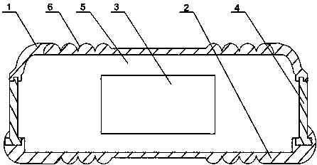
[0020] like figure 1 As shown, this embodiment includes an upper casing 1 and a lower casing 2, and the upper casing and the lower casing 2 are connected to each other by rubber blocks 4 to form a closed cavity, and a chip 3 is fixed in the cavity, and the chip 3 and the cavity are provided with fillers 5, and two elastic connecting parts 6 are respectively provided on the outer walls of the upper casing 1 and the lower casing 2, and the width of the connecting parts 6 is the total width of the upper casing 1. a quarter of the width. The work of the present invention is an improvement to the existing bus IC card shell, and the upper casing 1, the lower casing 2 and the rubber block 4 are surrounded to form a cavity, the cavity is provided with a filler 5, and the bus chip 3 is placed In the center of the cavity, when the IC card is impacted or dropped from a high place, the filler 5 can play a certain role in buffering and protecting the chip 3 to avoid damage to the chip 3; ...
Embodiment 2
[0023] like figure 1 As shown, in this embodiment, on the basis of Embodiment 1, the four connecting parts 6 are arranged symmetrically on the outer walls of the upper casing 1 and the lower casing 2 centering on the cavity. Four elastic connecting parts 6 are symmetrically distributed in pairs on the upper casing 1 and the lower casing 2. When the surface of the IC card is impacted by an external force, the elastic recovery of the connecting parts 6 can be superimposed to the maximum, and the direction is consistent with the direction of the external force. On the contrary, to the greatest extent offset the distortion caused by the external force acting on the card surface.
[0024] Preferably, the cross section of the connecting portion 6 is wavy. The connection portion 6 with a wavy cross section can generate a relatively large amount of deformation per unit area, which can further improve the buffer protection of the upper shell 1 and the lower shell 2 .
PUM
 Abstract
Description
Claims
Application Information
 - R&D Engineer
- R&D Manager
- IP Professional
- Industry Leading Data Capabilities
- Powerful AI technology
- Patent DNA Extraction
Browse by: Latest US Patents, China's latest patents, Technical Efficacy Thesaurus, Application Domain, Technology Topic, Popular Technical Reports.
© 2024 PatSnap. All rights reserved.Legal|Privacy policy|Modern Slavery Act Transparency Statement|Sitemap|About US| Contact US: help@patsnap.com