Plunger pair friction measurement device with rotating cylinder body

A measuring device and friction technology, applied in measuring devices, force/torque/work measuring instruments, instruments, etc., can solve the problem of inability to simulate the high-frequency vibration of the cylinder block, the centrifugal motion of the plunger, and the inability to simulate the centrifugal force of the plunger. Ignore and other problems, to achieve the effect of simple and reliable measurement structure, simple and reliable sensor wiring and installation, and small changes

Active Publication Date: 2014-12-10
ZHEJIANG UNIV
View PDF6 Cites 17 Cited by
  • Summary
  • Abstract
  • Description
  • Claims
  • Application Information

AI Technical Summary

Problems solved by technology

Although these devices can be close to the actual working conditions of the pump in terms of pressure, they cannot simulate the high-frequency vibration of the cylinder and the vortex of the plunger in the plunger cavity. At the same time, the centrifugal force of the plunger cannot be ignored under high-speed and heavy loads. The measuring device cannot simulate the centrifugal movement of the plunger
[0004] In the research on the friction measurement device of the plunger pair using cylinder rotation, the "friction pump" test bench built by Purdue University in th...

Method used


Image

  • Plunger pair friction measurement device with rotating cylinder body
  • Plunger pair friction measurement device with rotating cylinder body
  • Plunger pair friction measurement device with rotating cylinder body

Examples


Embodiment Construction

[0019] The present invention will be further described below in conjunction with accompanying drawing.

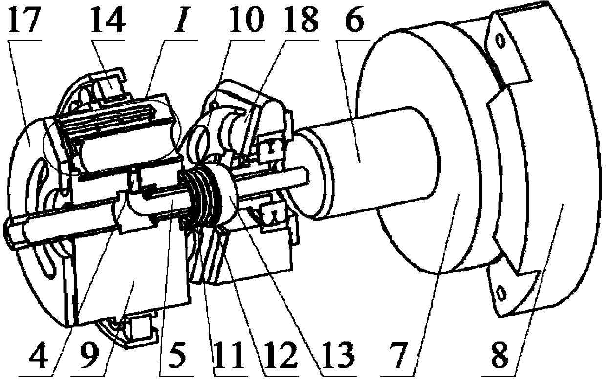
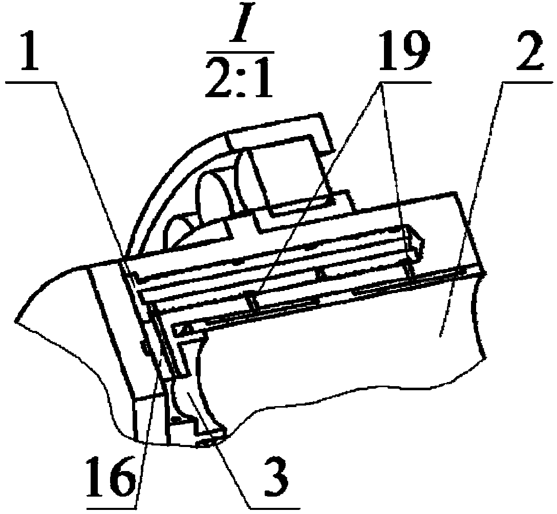
[0020] Such as figure 1 , figure 2 , image 3 As shown, the present invention includes a spiral groove type capillary restrictor 1, a floating bush 2, a diversion boss 3, a ball head force measuring contact rod 4, a force measuring connecting rod 5, a connecting rod chuck 6, a rotatable multi-dimensional Force sensor 7, wireless data acquisition device 8, axial piston pump cylinder 9, return plate 10, spring retaining ring 11, preload spring 12, center ball hinge 13, cylinder outer ring cylindrical roller bearing 14, housing Connecting oil channel 15, pressure oil channel 16, distribution plate 17, swash plate 18, static pressure bearing oil supply hole 19, hollow main shaft 20 on the side of the distribution plate, hollow main shaft 21 on the side of the swash plate; axial piston pump cylinder One of the plunger holes in 9 is enlarged to fit with the floating bush 2 in...


PUM


Abstract

A plunger pair friction measurement device with a rotating cylinder body mainly comprises spiral groove type capillary throttling devices, a floating liner, a flow guide boss, a ball head force measurement touch rod, a force measurement connecting rod, a connecting rod chuck, a rotatable multi-dimensional force sensor, a wireless data collection device, the cylinder body, a casing communication oil lead duct, a pressure oil lead duct and a static pressure bearing oil supply hole; the three spiral groove type capillary throttling devices which are distributed on the circumference in an equally spaced mode are used for leading the pressure oil in a plunger chamber into a static pressure chamber which is formed on the outer surface of the floating liner through the pressure oil lead duct and the static pressure bearing oil supply hole to form a static pressure bearing assembly; the cylinder body cylindrical surface of the plunger chamber area is provided with the casing communication oil lead duct; a ball head of the force measurement touch rod is embedded in the floating liner so as to transfer the friction force of a plunger to the rotatable multi-dimensional force sensor through the force measurement connecting rod and the connecting rod chuck; the wireless data collection device is fixed; a small gap is reserved between the wireless data collection device and the sensor; data are transmitted out through a cable which is arranged on the wireless data collection device.

Description

technical field [0001] The invention relates to a measuring device for the frictional force of a rotary plunger pair of an axial plunger pump cylinder, which is particularly suitable for measuring the frictional force of a plunger pair of a high-pressure, high-speed, small-size axial plunger pump in the aviation field. Background technique [0002] Due to the advantages of high power density and compact structure, axial piston pumps are widely used in various industrial and civil equipment. It is especially important for aviation piston pumps to achieve high power-to-weight ratio and high efficiency. Research on efficiency and energy saving and life extension has never stopped. The main factor affecting the efficiency of the plunger pump is the friction loss of the friction pair. The friction loss of the plunger pair and the wear of the moving parts are more serious under high-speed and heavy-load conditions. The friction measurement device of the plunger pair of the pump i...

Claims


Application Information

Patent Timeline
IPC IPC(8): G01L5/00
Inventor 徐兵陈媛张军辉葛耀峥
Owner ZHEJIANG UNIV
Why Eureka
Try Eureka