
Rectangular opening sound transmission rate and sound transmission loss computing method

A technology with a rectangular opening and a calculation method, which is applied in the measurement of ultrasonic/sonic/infrasonic waves, measuring devices, instruments, etc., and can solve the problems of slow calculation speed, inability to obtain sound transmission rate and sound transmission loss, etc.

Active Publication Date: 2014-12-10
HEFEI UNIV OF TECH
View PDF6 Cites 7 Cited by
  • Summary
  • Abstract
  • Description
  • Claims
  • Application Information

AI Technical Summary

Problems solved by technology

[0006] These methods have certain effects and have their own characteristics when calculating specific types of openings, but they also have certain limitations
For example, the acoustic transmission loss calculation formula derived based on the plane wave theory can only be used to calculate the acoustic transmission loss below the cutoff frequency of the plane wave
Although the modal-based acoustic transmission loss calculation formula can calculate the total acoustic transmission rate and acoustic transmission loss, it cannot calculate the acoustic transmission rate and acoustic transmission loss of the opening in any one or multiple modes, and when the frequency is very High, when the number of modes is high, the calculation speed is slow

Method used


Image

  • Rectangular opening sound transmission rate and sound transmission loss computing method
  • Rectangular opening sound transmission rate and sound transmission loss computing method
  • Rectangular opening sound transmission rate and sound transmission loss computing method

Examples


Embodiment Construction

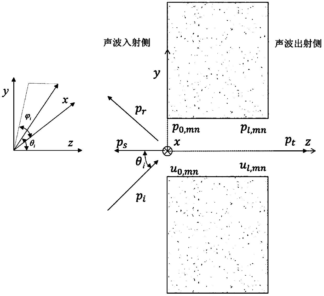
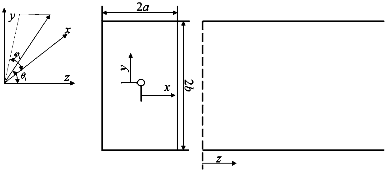
[0069] see figure 1 , figure 2 , the method for calculating the sound transmission rate and sound transmission loss of a rectangular opening in this embodiment is:

[0070] For a rectangular opening that runs through the wall, the sound wave incident side of the rectangular opening is on one side of the wall, and the sound wave exit side of the rectangular opening is on the other side of the wall. The width of the rectangular opening section on the incident side is 2a, the length is 2b, and the area is S 1 , the width of the rectangular opening section on the exit side is 2a, the length is 2b, and the area is S 2 , and have S 1 = S 2 , the calculation of sound transmission rate and sound transmission loss of a rectangular opening is carried out as follows:

[0071] Step a, define the coordinate system

[0072] Take the center of the sound wave incident side section of the rectangular opening as the coordinate origin, take the direction perpendicular to the sound wave in...


PUM


Abstract

The invention discloses a rectangular opening sound transmission rate and sound transmission loss computing method. The method comprises, firstly, defining a rectangular-opening coordinate system, and establishing force balance formulas of both cross sections of the opening and the sound transmission matrixes at both ends of the opening; secondly, utilizing the properties of sound radiating impedance of vibration of air layers at both ends of the opening to achieve computation of the sound transmission rate of a rectangular opening single-level mode under the condition of parallel sound wave incidence; thirdly, superpositioning the sound transmission rate of every level of mode to obtain the sound transmission rate of the rectangular opening; fourthly, integrating incident angles to obtain the sound transmission rate of the rectangular opening under the condition of scattered sound field incidence; lastly, calculating the sound transmission losses of the rectangular opening under the condition of the scattered sound field incidence through a relation between sound transmission losses and sound transmission rates. The rectangular opening sound transmission rate and sound transmission loss computing method can be used for computing the sound transmission rates or the sound transmission losses of one or more certain levels as well as computing total sound transmission rates or total sound transmission losses, thereby greatly improving the computing flexibility, and meanwhile, by omitting the influence of the very small sound radiating impedance of both a part of real parts and a part of imaginary parts, greatly improves the calculating speed.

Description

technical field [0001] The invention relates to a method for calculating the sound transmission rate and sound transmission loss of a rectangular opening on a wall in the field of noise in the specialty of physics, in particular to a method capable of calculating the shape of a rectangular opening on both sides of the wall. Calculation method of acoustic transmission rate and acoustic transmission loss of openings with finite depth and need to consider high-order wave components (need to consider high-order modes). Background technique [0002] Openings are mainly divided into large openings, small and medium holes, and micropores. [0003] For micropores, academician Ma Dayou, a famous Chinese scholar, and his research team have conducted in-depth research, and many domestic and foreign scholars have also conducted a lot of research. [0004] For small and medium holes, because their size is not very large, the frequency range of the research is often below the cut-off fre...

Claims


Application Information

Patent Timeline
IPC IPC(8): G01H17/00
Inventor 陈剑李家柱
Owner HEFEI UNIV OF TECH
Learn More