
Combined Long Distance Shaft Sleeve Coaxiality Detector

A technology of coaxiality and long spacing, applied in the field of combined long spacing bushing coaxiality detector, can solve the problems of large volume, heavy weight and damage of rear axle 1, achieve quick and convenient operation and reduce testing cost , cleverly conceived effect

Active Publication Date: 2017-01-25
GREAT WALL MOTOR CO LTD
View PDF7 Cites 0 Cited by
  • Summary
  • Abstract
  • Description
  • Claims
  • Application Information

AI Technical Summary

Problems solved by technology

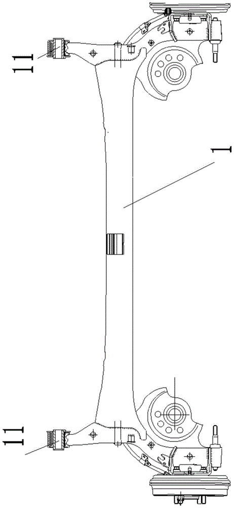
However, due to the relatively large dimensional tolerance of the two shaft sleeves relative to the center of the coil spring (greater than the coaxiality requirement), ordinary coaxiality special inspection tools cannot detect it. At present, three-coordinate testing equipment is generally used to detect the coaxiality. The detection principle of the coordinate detection equipment is as follows: connect the center points of the outermost rings of the two bushings 11 to construct a common axis, and then obtain the coaxiality between the axes of each bushing 11 and the common axis to judge whether it meets the requirements
It has the following disadvantages: the three-coordinate detection equipment is a high-precision detection equipment, which is used to detect workpieces with low coaxiality accuracy requirements, which wastes resources and makes the detection cost high; the rear axle 1 is large in size and heavy It is easy to cause damage to the rear axle 1 and the three-coordinate detection equipment

Method used


Image

  • Combined Long Distance Shaft Sleeve Coaxiality Detector
  • Combined Long Distance Shaft Sleeve Coaxiality Detector
  • Combined Long Distance Shaft Sleeve Coaxiality Detector

Examples


Embodiment Construction

[0028] It should be noted that, in the case of no conflict, the embodiments of the present invention and the features in the embodiments can be combined with each other.

[0029] The key innovation point of the present invention is to simulate the three-coordinate principle, and the two ends of the combined structure are respectively the common axis of the center points of the outermost rings of the two bushings 11 .

[0030] The present invention will be described in detail below with reference to the accompanying drawings and examples.

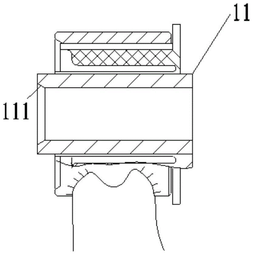
[0031] like image 3 , 4 , 5, the combined long-distance shaft sleeve coaxiality detector includes a sliding end shaft 2, a reference rod 3 and a detection sliding sleeve 4, and there are two sliding end shafts 2, and the sliding end shaft 2 includes a The chamfered fitting part 22 matched with the chamfered part 111 of the bushing also includes a sliding pin part 23 that can extend into the bushing 11;

[0032] Both ends of the reference...


PUM


Abstract

The invention provides a coaxiality detector for a combined long-spaced shaft sleeve. The coaxiality detector comprises sliding end shafts, a reference rod and detection sliding sleeves, wherein two sliding end shafts are provided; the sliding end shafts comprise chamfered fitting portions and sliding pin portions; the two ends of the reference rod are provided with end stepped holes; two detection sliding sleeves are provided; the detection sliding sleeves have tubular structures provided with through holes; the through holes are sliding sleeve sliding holes; the sliding sleeve sliding holes are in clearance fit with the sliding pin portions of the sliding end shafts; the difference between the inner diameter of the shaft sleeve and the outer diameter of each detection sliding sleeve is smaller than a preset coaxiality standard value of the shaft sleeve. In the detector, the sliding end shafts and the reference rod are combined into a public axis, and inspection on whether the coaxiality between shaft sleeves at the two ends of a rear axle and the public axis meets a design standard or not is performed by detecting whether the sliding sleeves can be inserted into the gaps between the sliding pin portions of the sliding end shafts and the shaft sleeves. The coaxiality detector is skillful in design, and is rapid and convenient to operate and use.

Description

technical field [0001] The invention relates to an instrument for detecting whether the coaxiality of long-distance shaft sleeves is qualified or not, in particular to a combined long-distance shaft sleeve coaxiality detector. Background technique [0002] In the field of automobile manufacturing and assembly, such as figure 1 As shown in the schematic diagram of the rear axle structure, the structure of the rear axle 1 is complex, and the bushings 11 at both ends are connected to the vehicle body. Concentricity is tested with respect to its common axis. However, due to the relatively large dimensional tolerance of the two shaft sleeves relative to the center of the coil spring (greater than the coaxiality requirement), ordinary coaxiality special inspection tools cannot detect it. At present, three-coordinate testing equipment is generally used to detect the coaxiality. The detection principle of the coordinate detection equipment is: connect the center points of the oute...

Claims


Application Information

Patent Timeline
IPC IPC(8): G01B5/252
Inventor 王惠敏崔玉梅张晓叶刘信亮盖立斌刁凡荣殷大鹏王峰
Owner GREAT WALL MOTOR CO LTD
Learn More