Rotary type fluid passage changeover valve

A flow path switching and rotary technology, applied to valve details, multi-way valves, safety valves, etc., can solve problems such as increasing motor input torque, wear of moving parts, and uncertain air pressure

Inactive Publication Date: 2014-12-10
ZHEJIANG SANHUA ROTARY VALVE
View PDF5 Cites 8 Cited by
  • Summary
  • Abstract
  • Description
  • Claims
  • Application Information

AI Technical Summary

Problems solved by technology

[0004] The purpose of the present invention is to provide a rotary flow switching valve to solve the problems in the prior art that the input torque of the motor is increased and the moving parts are worn due to the uncertain air pressure between the upper and lower chambers formed by the valve core and the valve body.

Method used


Image

  • Rotary type fluid passage changeover valve
  • Rotary type fluid passage changeover valve
  • Rotary type fluid passage changeover valve

Examples


Embodiment Construction

[0025] It should be noted that, in the case of no conflict, the embodiments in the present application and the features in the embodiments can be combined with each other. The present invention will be described in detail below with reference to the accompanying drawings and examples.

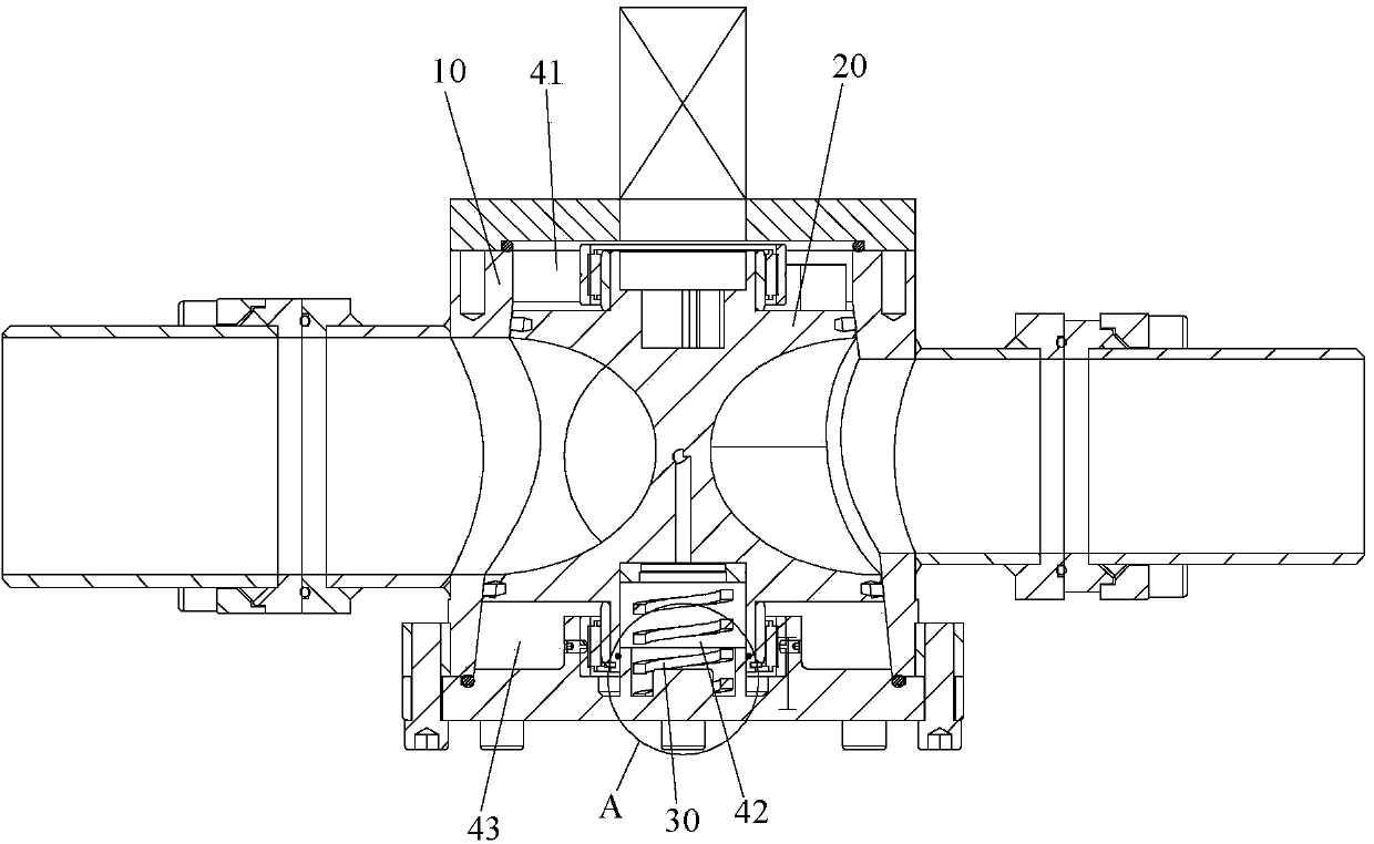
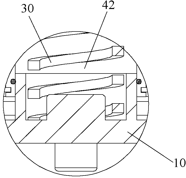
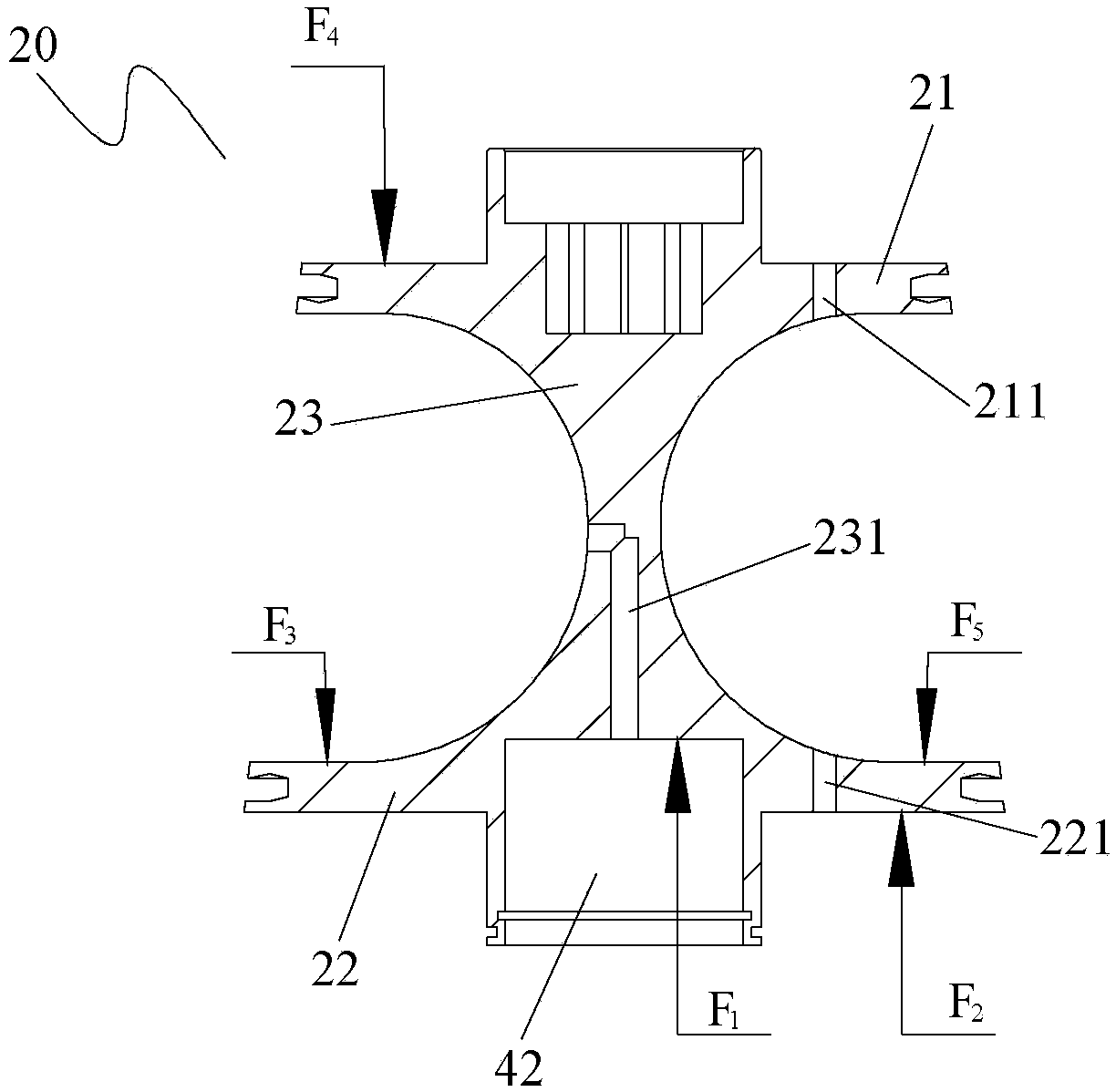
[0026] Such as Figure 1 to Figure 5 As shown, the rotary flow switching valve of this embodiment includes: a valve body 10 , a valve core 20 , a driving device and an elastic member 30 . In the above structure, the valve body 10 has a valve cavity, the valve cavity is in the shape of a frustum of a cone, the valve core 20 is adapted to the shape of the valve cavity, and the valve core 20 is rotatably arranged in the valve cavity, the valve core 20 and the valve body 10 Independent high-pressure passages and low-pressure passages are formed between the side walls. The spool 20 has a first end and a second end along its axis. The area of ​​the first end of the spool 20 is smaller than the area ...


PUM


Abstract

The invention provides a rotary type fluid passage changeover valve. The rotary type fluid passage changeover valve comprises a valve body, a valve element, a driving device and an elastic part, wherein the valve body is provided with a valve cavity; the valve element is arranged in the valve cavity in a rotatable mode, and a high-pressure channel and a low-pressure channel which are independent of each other are formed between the valve element and the side walls of the valve body; the driving device is located at the first end of the valve element and is in drive connection with the valve element so as to drive the valve element to rotate; the elastic part is located at the second end of the valve element and abuts against the valve body and the valve element respectively, a first cavity is formed between the first end of the valve element and the valve body, a second cavity and a third cavity which are independent of each other are formed between the second end of the valve element and the valve body, and the third cavity is located in the outer side of the circumferential direction of the second cavity; at least one of the first cavity, the second cavity and the third cavity is communicated with the high-pressure channel, and the remaining cavities of the first cavity, the second cavity and the third cavity are communicated with the low-pressure channel. The problems of increase of input torque of a motor and abrasion to moving parts in the prior art are effectively solved according to the technical scheme.

Description

technical field [0001] The invention relates to the technical field of switching valves, in particular to a rotary flow path switching valve. Background technique [0002] In the prior art, the rotary flow path switching valve utilizes a driving device to lift the valve core and compress the valve core, so as to realize switching and reset sealing of the switching valve. The driving device includes a motor and a transmission mechanism, and the reversing process of the switching valve depends on the transmission and transformation of the rotation of the motor through the transmission structure. [0003] Due to the existence of internal leakage in the rotary flow switching valve, pressure will be generated in the upper and lower chambers formed by the valve core and the valve body, and the air pressure in the upper and lower chambers is between high and low pressure. Under the action of the air pressure, the spool has a resultant force that clings to the valve body, and the w...

Claims


Application Information

Patent Timeline
Patent Type & Authority Applications(China)
IPC IPC(8): F16K47/02F16K11/08F16K31/12F16K31/04F16K17/22
CPCF16K11/08F16K5/08
Inventor 廖洪练
Owner ZHEJIANG SANHUA ROTARY VALVE
Why Eureka
Try Eureka