Pull type hydrofoil device

A pulling type, hydrofoil technology, applied in transportation and packaging, hydrodynamic characteristics/hydrostatic characteristics, ship construction, etc. smooth effect

Inactive Publication Date: 2014-12-10
EAST CHINA UNIV OF SCI & TECH
View PDF5 Cites 2 Cited by
  • Summary
  • Abstract
  • Description
  • Claims
  • Application Information

AI Technical Summary

Problems solved by technology

Since the biasing mechanism is arranged at the front end of the hydrofoil device, it is far away from the driving platform arranged at the rear end of the hydrofoil device, and the two are connected by multiple rods, so there is a transmission loss of the pedaling force during operation. The operator must push the driving platform hard to overcome the bias. In this way, the operator's physical strength is exhausted very quickly, and the operator can only play for 2 to 4 minutes at a time, which seriously affects people's interest in using the product.
[0003] In order to improve the above technical problems, a self-propelled hydrofoil device disclosed in the Chinese invention patent "self-propelled hydrofoil device" (application publication number: CN103043177A) includes a guide mechanism, a steering rod, a steering support shaft, Operator's pedal, frame support and rear wing, one end of the steering support shaft is connected to the steering rod, and the other end is connected to the frame support with a pedal rotation and reset mechanism, which includes an integral body with the frame support The hinge seat and the hinge plate integrated with the steering support shaft, the upper end of the hinge plate is hinged with the upper end of the hinge seat, the lower end of the hinge seat is fixed with a limit connecting rod, and the lower end of the hinge plate slides on the limit link. The rod is also sleeved with a return spring or elastic body used to control the opening and closing angle of the hinge plate and the hinge seat. One end of the return spring or elastic body is against the hinge plate, and the other end is against the nut at the end of the limit connecting rod. The pedal return mechanism can make the rear wing cut into the water to generate forward propulsion when the operator pedals the operating pedal, which can improve the conversion rate of force when pedaling, reduce the physical consumption of the operator, and can be used when the operator stops During the pedaling operation, the rear wing is lifted back to the water surface sliding state. The pedal reset mechanism is an important mechanism for the hydrofoil device to move forward on the water, and it converts the work done by the operator's pedaling operation into the hydrofoil device. However, the above-mentioned hydrofoil device only provides power by the pedals, and the hands only play a role in controlling the direction, which is inconvenient to coordinate the whole body, and the pedals exert a large force

Method used


Image

  • Pull type hydrofoil device
  • Pull type hydrofoil device
  • Pull type hydrofoil device

Examples


Embodiment Construction

[0030] The pulling type hydrofoil device of the present invention will be further described in detail below in conjunction with the accompanying drawings.

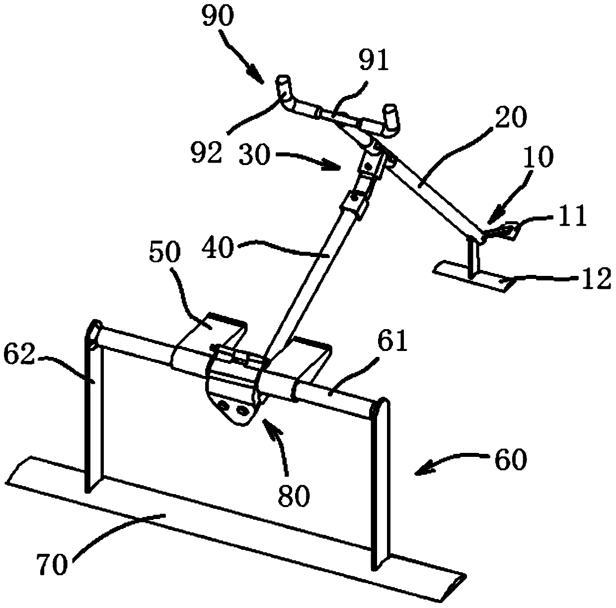
[0031] like figure 1 As shown, the pull type hydrofoil device of the present invention is made up of guide mechanism 10, rotating rod 20, reset mechanism 30, support rod 40, pedal 50, frame support 60, rear wing 70, buffer mechanism 80 and handle 90.

[0032] Guide mechanism 10 is made up of floating plate 11 and front wing 12. The floating sheet 11 mainly plays the role of tracking the water surface and keeping the front wing 12 in a horizontal state. The front wing 12 mainly makes the water generate lift to it during the forward process of the hydrofoil device, and jointly maintains the hydrofoil device floating on the water surface with the rear wing 70 above.

[0033] Resetting mechanism 30 is made up of sleeve 31, elastic body 32 and the connecting seat 33 with square notch fixed on the upper end of support rod 40. ...


PUM


Abstract

The invention discloses a pull type hydrofoil device. The pull type hydrofoil device comprises a supporting frame, a rotation rod, a supporting rod and a handle. A rear wing is arranged at the lower end of the supporting frame, and two spaced pedals are arranged at the upper end of the supporting frame. A guide mechanism is arranged at one end of the rotation rod. One end of the supporting rod is connected with the rotation rod through a reset mechanism. A buffer mechanism is arranged at the upper end of the supporting frame, and the other end of the supporting rod is connected with the buffer mechanism. The handle is arranged at the other end of the rotation rod. According to the pull type hydrofoil device, when an operator pulls the handle backwards, impact to the supporting frame from the supporting rod can be reduced due to the buffer mechanism; the buffer mechanism can store elastic potential energy and release the stored energy when the operator steps on the pedals, and therefore the pedaling operation saves more labor and is more convenient.

Description

technical field [0001] The invention relates to a device driven by the operator to move forward on the water surface, in particular to a pulling type hydrofoil device. Background technique [0002] Chinese invention patent "self-propelled hydrofoil device" (application publication number: CN1544288A) discloses a self-propelled hydrofoil device, which includes a first hydrofoil, a second hydrofoil and a connecting first hydrofoil and a second hydrofoil. The hydrofoil is equipped with a steering structure and a supporting structure of a driving platform. The steering structure includes a steering handle and a first rotating shaft part and a second rotating shaft part that are independent of each other. The first rotating shaft part and the second rotating shaft part are movable to each other. and the movable connection point is located in front of the steering handlebar, the first shaft part and the second shaft part are movable between a first position and a second position, ...

Claims


Application Information

Patent Timeline
IPC IPC(8): B63B1/28B63H1/36B63H16/08
CPCB63B1/26B63H1/30B63H16/08B63H2016/005
Inventor 钟豪李锦
Owner EAST CHINA UNIV OF SCI & TECH
Why Eureka
Try Eureka