
VHP sterilization device and method

A sterilizing device and sterilizing chamber technology, which is applied in heating methods, household heating, space heating and ventilation details, etc., can solve the problems of low safety and poor sterilizing effect, so as to prevent pollution and improve sterilizing effect and safety effects

Active Publication Date: 2014-12-03
SHANGHAI YANFU PHARMA SYST ENG
View PDF4 Cites 11 Cited by
  • Summary
  • Abstract
  • Description
  • Claims
  • Application Information

AI Technical Summary

Problems solved by technology

[0003] The invention provides a VHP sterilization device and method to solve the problems of poor sterilization effect and low safety in the prior art

Method used


Image

  • VHP sterilization device and method
  • VHP sterilization device and method
  • VHP sterilization device and method

Examples


Embodiment 1

[0027] A VHP sterilization device provided in Embodiment 1 of the present invention is installed between the material area and the sterile area. Sterile area refers to the area that requires aseptic operation. In this area, personnel and related items must be kept in a sterile state. Therefore, when items are sent from the material area to the sterile area, they must be sterilized by a sterilization device. . When in use, the operator puts the items to be sterilized into the sterilization device on the side of the material area, and after sterilizing, take them out from the side of the aseptic area for use in the aseptic area.

[0028] The specific structure of the sterilization device is as follows: figure 1 As shown, it includes a gas source 1 , a hydrogen peroxide storage tank 2 , a sterilization chamber 3 , a dehumidification pipeline 4 , a sterilization pipeline 5 , a ventilation pipeline 6 and an exhaust pipeline 7 . The dehumidification pipeline 4 connects the gas sou...

Embodiment 2

[0051] A VHP sterilizing device provided in Embodiment 2 of the present invention, the pipeline arrangement structure of the sterilizing device is as follows: Figure 4 shown.

[0052] The dehumidification pipeline 4 and the sterilization pipeline 5 share an air source 1, which provides compressed air. The dehumidification pipeline 4 includes a first valve 41 and a dehumidifier 42 through which the gas source 1 is connected to the sterilization chamber 3 in sequence. The sterilization pipeline 5 includes a VHP generator 55, a preheater 51, a second valve 52, a metering pump 53 and a third valve 54, and the gas source passes through the preheater 51 and the second valve 52 to connect to the VHP generator in turn. The air input port of the device 55, the hydrogen peroxide storage 2 is connected to the hydrogen peroxide input port of the VHP generator 55 through the metering pump 53 and the third valve 54 in turn, and the output port of the VHP generator 55 is connected to the s...


PUM


Abstract

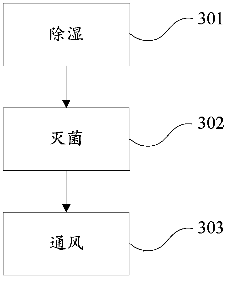
The invention discloses a VHP sterilization device and method. The sterilization device is arranged between a material area and a sterile area, and comprises an air source, a hydrogen peroxide storage device, a sterilization chamber, a dehumidification pipeline, a sterilization pipeline, a vent line and an air exhaust pipeline, wherein the dehumidification pipeline is connected with the air source and the sterilization chamber; the sterilization pipeline is connected with the air source, the hydrogen peroxide storage device and the sterilization chamber; the vent line is connected with the sterile area and the sterilization chamber; and the air exhaust pipeline is connected with the material area and the sterilization chamber. The sterilization method utilizing the sterilization device comprises three steps of dehumidifying, sterilizing and venting. Compared with the prior art, the scheme disclosed by the invention has the advantages that vapor hydrogen peroxide serves as a sterilizing medium, dehumidification, sterilization and ventilation are performed due to reasonable pipeline arrangement, and the sterilization effect and safety are effectively improved.

Description

technical field [0001] The invention relates to the field of sterilization equipment, in particular to a VHP sterilization device and method. Background technique [0002] The traditional clean room air sterilization technology mainly uses ozone or formaldehyde for disinfection or sterilization. However, with the development of sterile drug production, the requirements for the production environment, safety and environmental protection are getting higher and higher, and the negative impact of formaldehyde fumigation is getting worse. It has attracted more and more attention, and formaldehyde is easy to condense and absorb during the disinfection process, resulting in a large amount of residues. People staying in an environment with formaldehyde residues for a long time will do great harm to human health, and the bactericidal effect is not ideal. Therefore, this technology can no longer meet the requirements for sterilization in the field of pharmaceutical production. Conte...

Claims


Application Information

Patent Timeline
IPC IPC(8): A61L9/03F24F5/00F24F11/02F24F13/28
Inventor 直国富
Owner SHANGHAI YANFU PHARMA SYST ENG
Learn More