
Plugging device suitable for postoperation perivalvular leakage

An occluder and paravalvular technology, applied in the direction of heart valves, etc., can solve problems such as inconsistency of position and shape, large deformation of occluder, and unsuitability for the treatment of paravalvular leakage, and achieve the effect of appropriate tension

Inactive Publication Date: 2014-12-03
SHANDONG PROVINCIAL HOSPITAL
View PDF9 Cites 5 Cited by
  • Summary
  • Abstract
  • Description
  • Claims
  • Application Information

AI Technical Summary

Problems solved by technology

[0004] At present, the treatment methods for paravalvular leakage include: surgery and interventional methods. There is no special occluder for this operation. In clinical practice, patent ductus arteriosus occluders or interventricular septum are routinely used. The defect occluder, the main structure of the above-mentioned occluder is cylindrical, it is not suitable to be directly used in the operation of paravalvular leakage, because in the process of using the occluder for occlusion, the occluder and The position and shape of the paravalvular leak do not match, and it has poor adaptability, and there may be a bias phenomenon after occlusion
At the same time, in order to adapt to the shape of the paravalvular leak, the deformation of the occluder is relatively large, resulting in excessive tension on the suture site and forming a new leak point, so it is not suitable for the treatment of paravalvular leak
[0005] According to the applicant's knowledge, at present, there is no special occluder for occlusion of paravalvular leakage

Method used


Image

  • Plugging device suitable for postoperation perivalvular leakage
  • Plugging device suitable for postoperation perivalvular leakage
  • Plugging device suitable for postoperation perivalvular leakage

Examples


Embodiment Construction

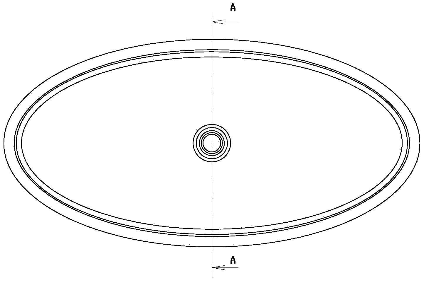
[0030] like Figure 1 to Figure 7 As shown, the present invention relates to an occluder suitable for postoperative paravalvular leakage. The occluder is composed of metal filaments, an impermeable membrane and a fixation element.

[0031] In view of the existing defects, the subject of protection of this patent is as follows:

[0032] What is developed is a medical device for occluding paravalvular leakage after mechanical valve surgery. The element makes the closure process full of flexibility through minimal damage and minimal intervention. The structure of this element is more in line with the anatomical and physiological structure of the mechanical valve and the suture site, and it is as close as possible to the leak point without reducing the In the case of high bonding strength, the element can reach the blocking site completely and accurately, and the tension is optimized to implement blocking, and the blocking effect and service life are significantly increased.

[...


PUM

PropertyMeasurementUnit
Thicknessaaaaaaaaaa

Abstract

The invention provides a plugging device suitable for postoperation perivalvular leakage. The plugging device comprises a fabric body and films. The fabric body is formed by a first oval area, a second oval area and a third oval area in the middle, wherein the first oval area and the second oval area are arranged on the two sides. The third oval area is shaped like a hollow oval cylinder with the ratio of a long axis to a short axis ranging from one third to two thirds. The fact that a mechanical valvula suture ring of the portion to be plugged is clamped can be used as a criterion for the thickness of the third oval area. The portion extends outwards by 0.2 mm-1 mm from the outer edge of the third oval area to form the edge of the second oval area. At least one unfolded film is arranged in a cavity in the third oval area. When the plugging device is used for plugging, the oval plugging device is arranged along a leakage point and has the deformation and self-adaptation features, after the plugging device is plugged into the leakage point, the self-adaptive deformation is generated, the leakage point is plugged completely, tension is proper, and the plugging device is more suitable for the interventional therapy of the perivalvular leakage.

Description

technical field [0001] The proposal relates to an occluder commonly used in interventional operations, specifically a special occluder suitable for postoperative paravalvular leakage. Background technique [0002] A mechanical valve is an artificial valve made of non-biological materials. Its basic structure includes three parts: a valve frame, a valve body, and a sewing ring. The cage ball valve is inlaid with a sphere made of silicon rubber in a cage made of stainless steel. The ball moves up and down in the cage to form closing and opening, and the blood flow at the valve mouth is peripheral. The side tilt disc frame is made of alloy or pyrolytic carbon. The disc is made of pyrolytic carbon material. The disc is suspended and clamped in the circular petal frame by a metal chain. Blood flow was semi-central. The double-leaf petal frame is made of pyrolytic carbon, and two semicircular leaflets made of pyrolytic carbon are embedded in the petal frame. The petals are like ...

Claims


Application Information

Patent Timeline
IPC IPC(8): A61F2/24
Inventor 王玉林
Owner SHANDONG PROVINCIAL HOSPITAL
Learn More