
Multifunctional cable tunnel inspection well

A technology for cable tunnels and inspection wells, which is applied in the field of cable tunnels and can solve problems affecting the life safety of maintenance personnel, backflow, and low depth

Active Publication Date: 2014-11-26
ZAOZHUANG LIYUAN ELECTRIC POWER DESIGN +2
View PDF6 Cites 6 Cited by
  • Summary
  • Abstract
  • Description
  • Claims
  • Application Information

AI Technical Summary

Problems solved by technology

[0002] Existing cable trenches and cable tunnels are generally only equipped with inspection openings or safety holes for personnel maintenance, and the distance between safety holes in tunnels in industrial factories or substations should not be greater than 75m
If effective ventilation facilities are not installed, the air in the ditch will be dirty, which will affect the life safety of maintenance personnel
Drainage slopes or diversion grooves are set at the bottom of the ditch, and after being collected into the sump, they are discharged to the nearest drainage inspection well through PVC pipes. Due to the depth of the cable tunnel (cable trench) plus the depth of the sump, it is generally more than the depth of the drainage pipe network. Low, can not effectively drain naturally or even pour back, resulting in a large amount of water in the cable tunnel (cable trench)
The cable trench is not equipped with lighting facilities, which is inconvenient for maintenance

Method used


Image

  • Multifunctional cable tunnel inspection well

Examples


Embodiment Construction

[0014] In order to make the implementation technical means, creative features, objectives and effects of the present invention easy to understand, the present invention will be further elaborated below in conjunction with specific illustrations.

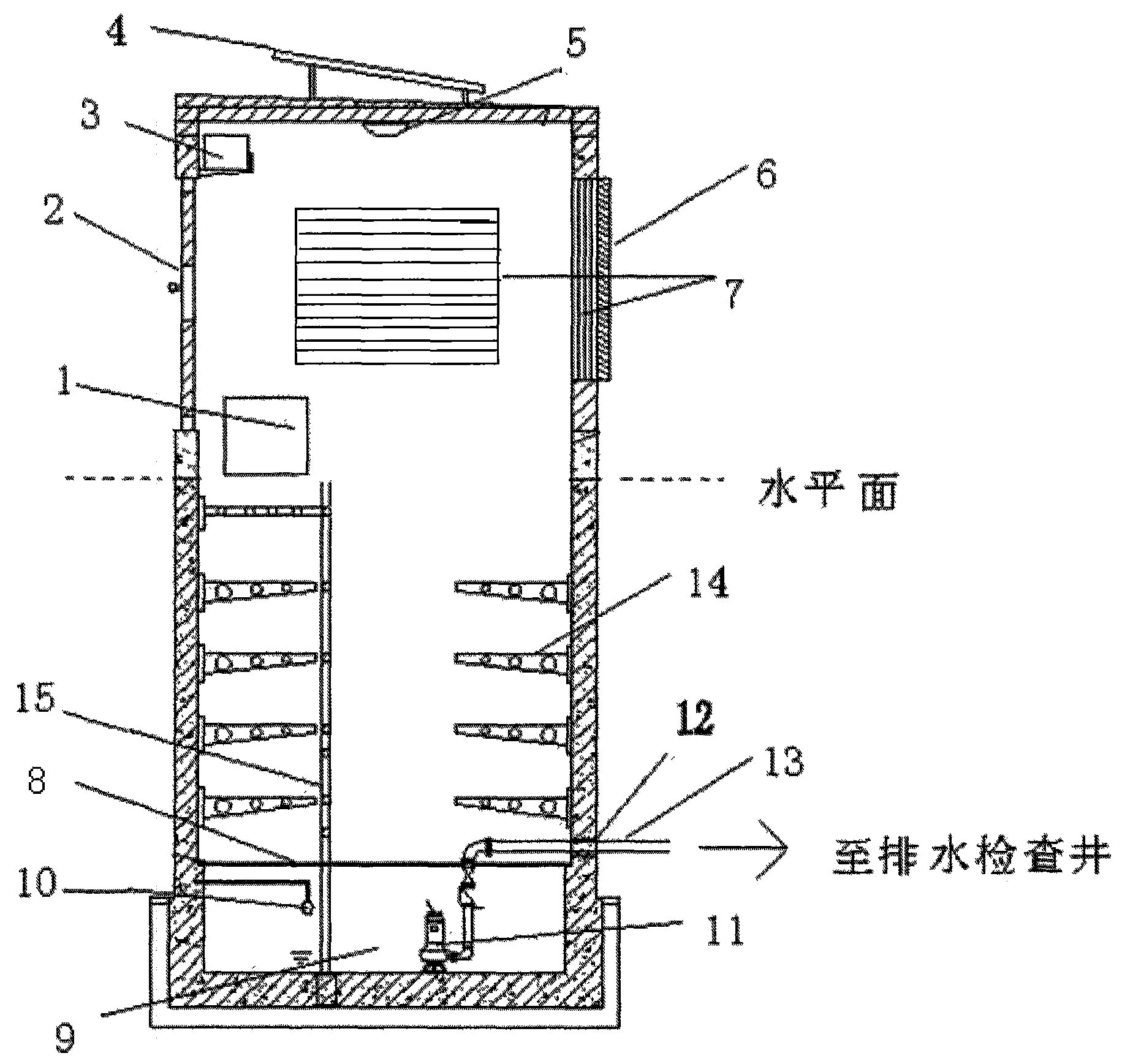
[0015] Such as figure 1 As shown, a cable tunnel multifunctional inspection well, including intelligent sewage control box 1, switch door 2, battery 3, solar panels 4, lamps 5, rain shutters 6, protective net 7, galvanized safety cover 8, A sump 9, a liquid level gauge 10, a submersible sewage pump 11, a flexible waterproof casing 12, a drainage pipe 13, a cable bracket 14, and a ladder 15. The intelligent sewage control box 1 is installed on one side of the upper house wall of the inspection well, The switch door 2 is arranged on the road surface of the upper house of the inspection well, the solar panel 4 is installed on the top of the upper house of the inspection well, and the battery 3 is installed in the upper house of the insp...


PUM


Abstract

The invention discloses a multifunctional cable tunnel inspection well. An intelligent sewage discharge control box is installed on one side of a house wall on the upper portion of the inspection well. A switch door is arranged on the road facing face of the portion, located on the upper portion of the inspection well, of a house. A solar cell panel is installed at the top of the portion, located on the upper portion of the inspection well, of the house. An accumulator is installed on the portion, located on the upper portion of the inspection well, in the house and connected with the solar cell panel. A lamp is installed at the top of the portion, located on the upper portion of the inspection well, of the house. Rainproof shutters are installed on three faces of the portions, located on the upper portion of the inspection well, of the house and protective nets are installed on the shutters. A galvanized safety cover board is installed on the upper portion of a water collection pit. A crawling ladder is located on the lower portion of the inspection well. A cable support is located in a cable trench and extends to the lower portion of the inspection well. The water collection pit is located on the lower portion of the inspection well. A liquid level meter is located in the water collection pit. A submersible sewage pump is located in the water collection pit. A flexible waterproof casing pipe is located on a wall penetrating portion of a water drainage pipe. The water drainage pipe is connected with the submersible sewage pump and connected to an external water drainage inspection well. The multifunctional cable tunnel inspection well is easy to install, convenient to maintain, attractive in appearance, capable of saving energy and environmentally friendly.

Description

technical field [0001] The invention relates to the field of cable tunnels, in particular to a multifunctional inspection shaft for cable tunnels. Background technique [0002] Existing cable trenches and cable tunnels are generally only equipped with inspection openings or safety holes for personnel maintenance, and the distance between safety holes in tunnels in industrial factories or substations should not be greater than 75m. If effective ventilation facilities are not installed, the air in the ditch will be dirty, which will affect the life safety of maintenance personnel. Drainage slopes or diversion grooves are set at the bottom of the ditch, and after being collected into the sump, they are discharged to the nearest drainage inspection well through PVC pipes. Due to the depth of the cable tunnel (cable trench) plus the depth of the sump, it is generally more than the depth of the drainage pipe network. Low, can not effectively drain naturally or even pour back, res...

Claims


Application Information

Patent Timeline
IPC IPC(8): E02D29/12H02S10/20
CPCY02B10/10Y02E10/50Y02E70/30
Inventor 孟梅邵明欣周芹王统民刘宝磊
Owner ZAOZHUANG LIYUAN ELECTRIC POWER DESIGN
Learn More