Magnetoelectric generator
a generator and magnetoelectric technology, applied in the direction of magnetic circuit rotating parts, mechanical energy handling, shape/form/construction of magnetic circuits, etc., can solve the problems of increasing manufacturing costs, and achieve the effect of reducing manufacturing costs, high ventilation efficiency, and reducing manufacturing costs
- Summary
- Abstract
- Description
- Claims
- Application Information
AI Technical Summary
Benefits of technology
Problems solved by technology
Method used
Image
Examples
embodiment 1
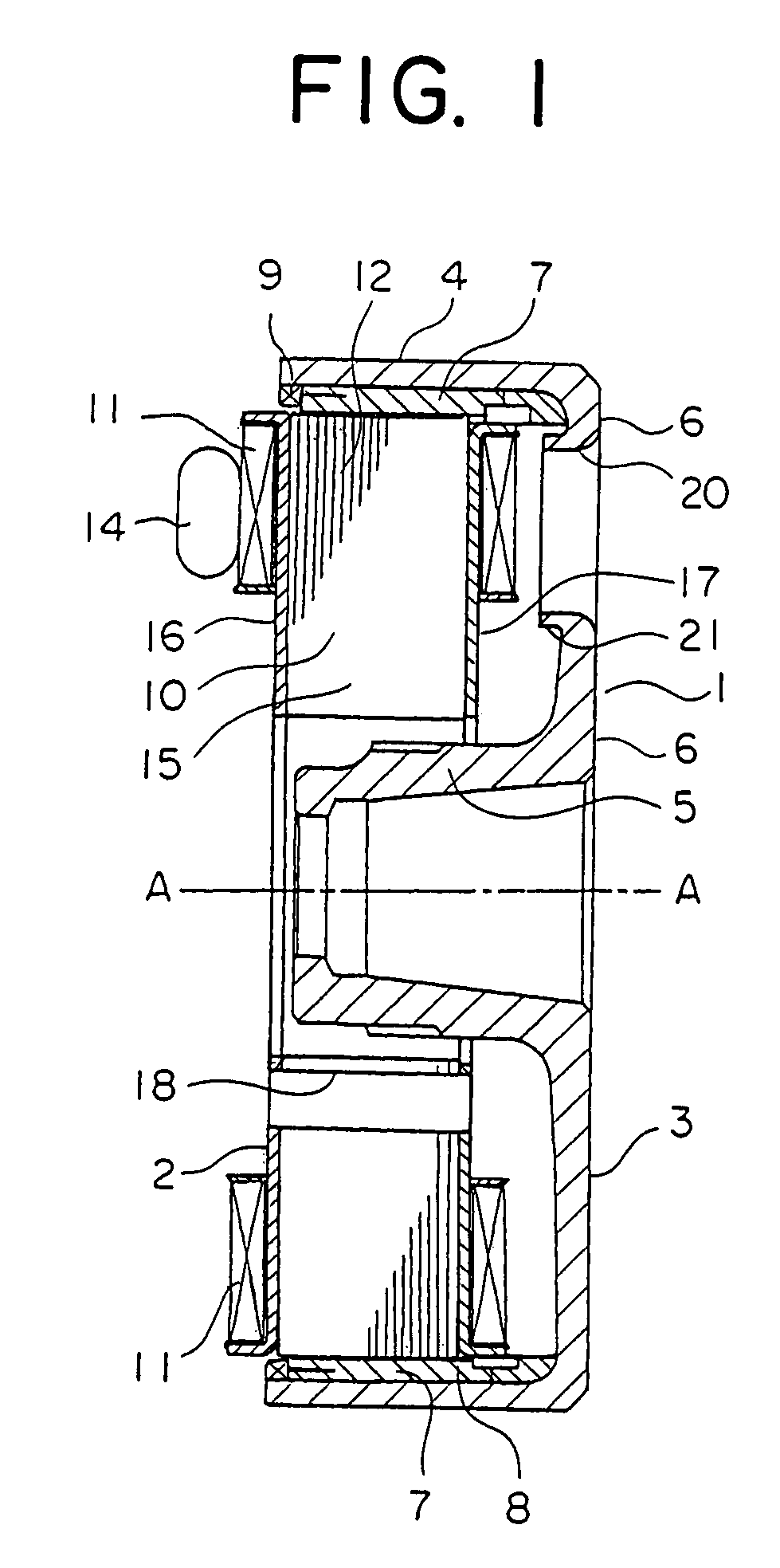
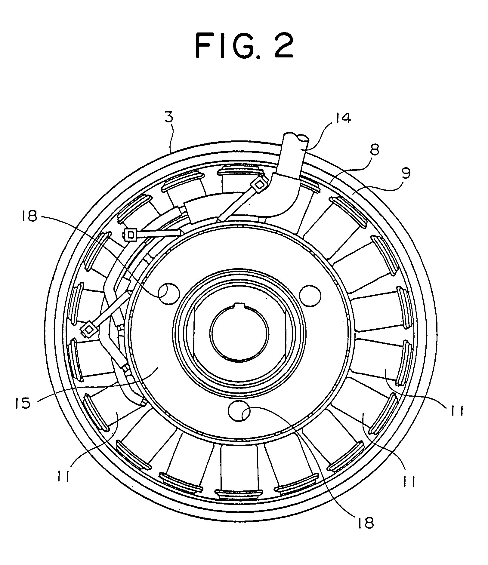
[0026]FIG. 1 is a vertical sectional view showing the magnetoelectric generator according to a first embodiment of the present invention and FIG. 2 is a side view of the same as viewed from the left-hand side in FIG. 1.
[0027]Referring to the figure, the magneto generator now under consideration includes a rotor 1 mechanically coupled to an internal combustion engine (not shown) and a stator 2 mounted on a stationary supporting member (not shown either) in opposition to the rotor 1.
[0028]The rotor 1 has a flywheel 3 of a substantially bowl-like shape which is composed of an outer peripheral cylindrical portion 4, a boss 5 formed at the inner side of the cylindrical portion 4 and a bottom portion 6 interconnecting the cylindrical portion 4 and the boss 5. The flywheel 3 is mounted rotatably about a rotation axis A—A. The boss 5 is fixedly secured to a rotatable shaft (not shown) driven by the internal combustion engine.
[0029]A plurality of permanent magnets 7 are fixedly mounted on th...
embodiment 2
[0046]FIG. 6 is a sectional view showing a major portion of the flywheel 3 of the magnetoelectric generator according to a second embodiment of the present invention. In the case of the magnetoelectric generator now concerned, a projection member 22 of a cylindrical shape having a collar 22a is press-fitted into each of the ventilation holes 20. The projection member 22 is made of an aluminum material which is a non-magnetic material exhibiting a high heat radiation property.
[0047]With the structure of the magnetoelectric generator according to the second embodiment of the invention, ventilation within the flywheel 3 can be promoted by press-fitting the projection member 22 into each of the ventilation holes 20, whereby electricity generation of high efficiency can be ensured similarly to the case of the magnetoelectric generator according to the first embodiment of the invention.
[0048]Further, since the collar 22a of the projection member 22 press-fitted into the ventilation hole 2...
embodiment 3
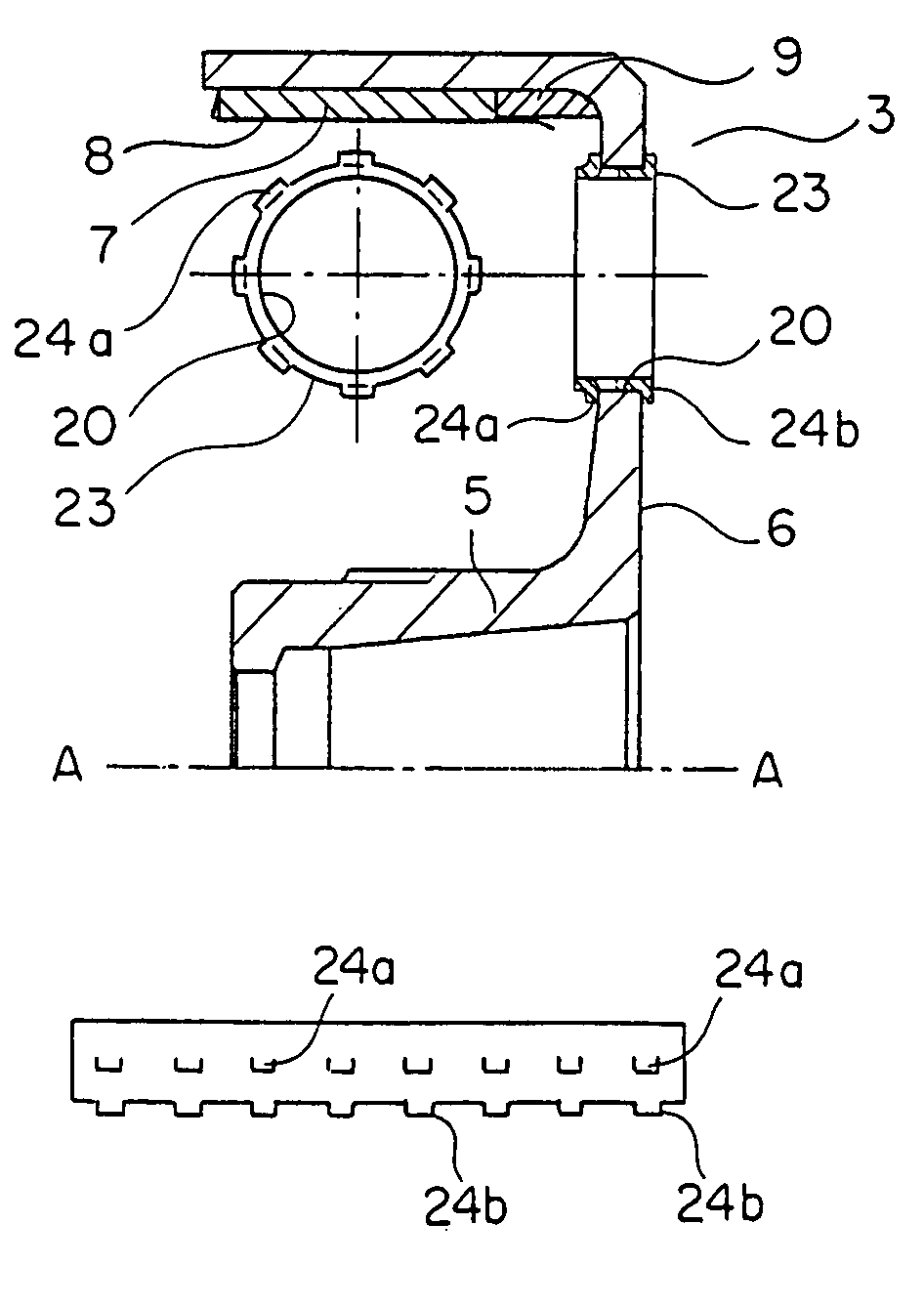
[0050]FIG. 7 is a sectional view showing a major portion of the flywheel3 of the magnetoelectric generator according to a third embodiment of the present invention. In the case of the magnetoelectric generator now concerned, a projection member 23 is fixedly secured to each of the ventilation holes 20. This projection member 23 is formed of a plate- or sheet-like member having a plurality of notched portions 24a and 24b formed equi-distantly (see FIG. 8) and bent or rolled into a cylindrical or sleeve-like form. After having inserted the projection member 23 of the cylindrical form into the ventilation hole 20, the notched portions 24a and 24b are bent so that the projection member 23 can be secured fixedly to the ventilation hole 20.
[0051]With the structure of the magnetoelectric generator according to the third embodiment of the invention, by securing the projection member 23 to the ventilation hole 20, ventilation within the flywheel 3 can be promoted, whereby high electricity ge...
PUM
 Abstract
Description
Claims
Application Information
 - R&D
- Intellectual Property
- Life Sciences
- Materials
- Tech Scout
- Unparalleled Data Quality
- Higher Quality Content
- 60% Fewer Hallucinations
Browse by: Latest US Patents, China's latest patents, Technical Efficacy Thesaurus, Application Domain, Technology Topic, Popular Technical Reports.
© 2025 PatSnap. All rights reserved.Legal|Privacy policy|Modern Slavery Act Transparency Statement|Sitemap|About US| Contact US: help@patsnap.com


