Pyrolysis device

A technology of pyrolysis and pyrolysis furnace, applied in the field of pyrolysis, which can solve the problems of easy blockage of oil and gas outlet pipelines, high operation difficulty, uneven heating of materials, etc., and achieve the effect of increasing single processing capacity, improving heat conduction, and improving thermal efficiency

Active Publication Date: 2016-03-30
SHENWU TECH GRP CO LTD
View PDF3 Cites 2 Cited by
  • Summary
  • Abstract
  • Description
  • Claims
  • Application Information

AI Technical Summary

Problems solved by technology

These pyrolysis devices have strict requirements on the particle size of the material, and have disadvantages such as low processing capacity, uneven heating of the material, serious secondary cracking of the material, easy blockage of the oil and gas outlet pipeline, high difficulty in operation, and short service life of the equipment.
Moreover, the quality of pyrolysis products is not high, and there are potential safety hazards

Method used


Image

  • Pyrolysis device
  • Pyrolysis device
  • Pyrolysis device

Examples


Embodiment Construction

[0022] Embodiments of the present invention are described in detail below, examples of which are shown in the drawings, wherein the same or similar reference numerals designate the same or similar elements or elements having the same or similar functions throughout. The embodiments described below by referring to the figures are exemplary and are intended to explain the present invention and should not be construed as limiting the present invention.

[0023] In describing the present invention, it should be understood that the terms "center", "longitudinal", "transverse", "length", "width", "thickness", "upper", "lower", "front", " Back", "Left", "Right", "Vertical", "Horizontal", "Top", "Bottom", "Inner", "Outer", "Axial", "Radial", "Circumferential", etc. The indicated orientation or positional relationship is based on the orientation or positional relationship shown in the drawings, and is only for the convenience of describing the present invention and simplifying the desc...


PUM


Abstract

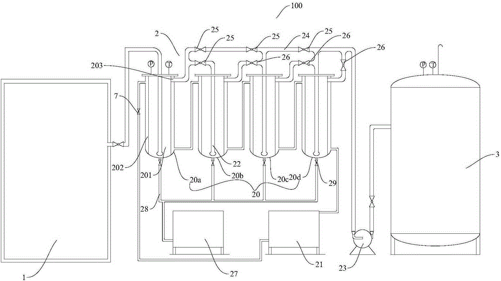
The invention discloses a pyrolyzer which comprises a pyrolyzing furnace, a cooler assembly and a gas storage tank, wherein the pyrolyzing furnace comprises a furnace body, two cloth boards and a heating radiation tube; the furnace body is provided with an oil-gas outlet; the two cloth boards are separately arranged in the furnace body in the up-and-down direction; each cloth board is provided with a plurality of through holes which are penetrative in the thickness direction; and the heating radiation tube is arranged in the furnace body and positioned between the two cloth boards. The cooler assembly is connected with the oil-gas outlet. The gas storage tank is connected with the cooler assembly and used for receiving pyrolysis gas. The pyrolyzer accelerates the material heating, enables the material to be heated uniformly, does not have coking, effectively increases the single-process treatment capacity, can fully utilize the radiation heat of the heating radiation tube, and has higher heat efficiency; and thus, the pyrolyzer is convenient for releasing the oil-gas mixture, and the generated oil-gas mixture contains fewer solid products, thereby avoiding the blockage of the oil-gas outlet.

Description

technical field [0001] The invention relates to the field of pyrolysis, in particular to a pyrolysis device. Background technique [0002] Pyrolysis technology is to heat organic matter to 500-1000°C in anaerobic or oxygen-deficient state, so that organic matter in solid waste can be converted into stored energy mainly consisting of gas, fuel oil and pyrolytic charcoal. Due to the anaerobic decomposition and reducing atmosphere, it can reduce the secondary pollution of sulfur, nitrogen, heavy metals and other harmful components in the waste to the environment, and there is no need for expensive scrubbing devices in the process. [0003] The low-temperature retort furnace disclosed in the related art adopts the method of setting electric heating rods around the outside of the retort furnace for heating. This heating method makes the material near the fireplace heat up quickly, and the material in the center of the furnace heats up slowly, and there is a problem of uneven heat...

Claims


Application Information

Patent Timeline
Patent Type & Authority Patents(China)
IPC IPC(8): C10G1/00C10B47/02
Inventor 吴道洪吴小飞肖磊
Owner SHENWU TECH GRP CO LTD
Why Eureka
Try Eureka