
Device for attaching elevator guide rail

A technology for installation devices and guide rails, which is applied in transportation, packaging, elevators, etc., can solve the problems of elastic body anti-vibration performance decline, deterioration over time, etc., and achieve the effect of delaying deterioration over time

Inactive Publication Date: 2014-11-19
HITACHI LTD
View PDF8 Cites 10 Cited by
  • Summary
  • Abstract
  • Description
  • Claims
  • Application Information

AI Technical Summary

Problems solved by technology

[0013] In the prior art, the elastic body is clamped between the guide rail and the bracket, and is fixed indiscriminately by the fastening torque of the guide rail and the guide rail clamp, so it may cause excessive pressure to act on the elastic body, so that the elastic body The anti-vibration performance declines, and the aging deterioration occurs prematurely
In addition, adequate countermeasures are not taken for welding fixation between brackets

Method used


Image

  • Device for attaching elevator guide rail
  • Device for attaching elevator guide rail
  • Device for attaching elevator guide rail

Examples


Embodiment 1

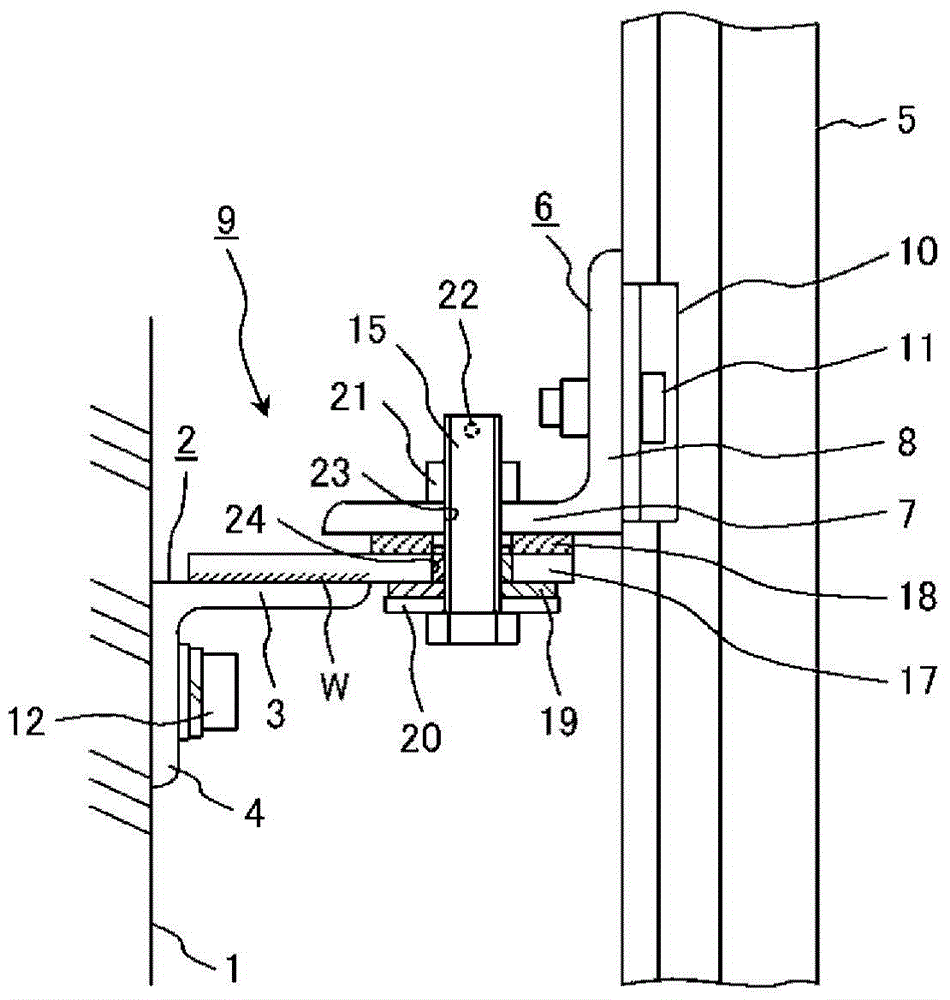
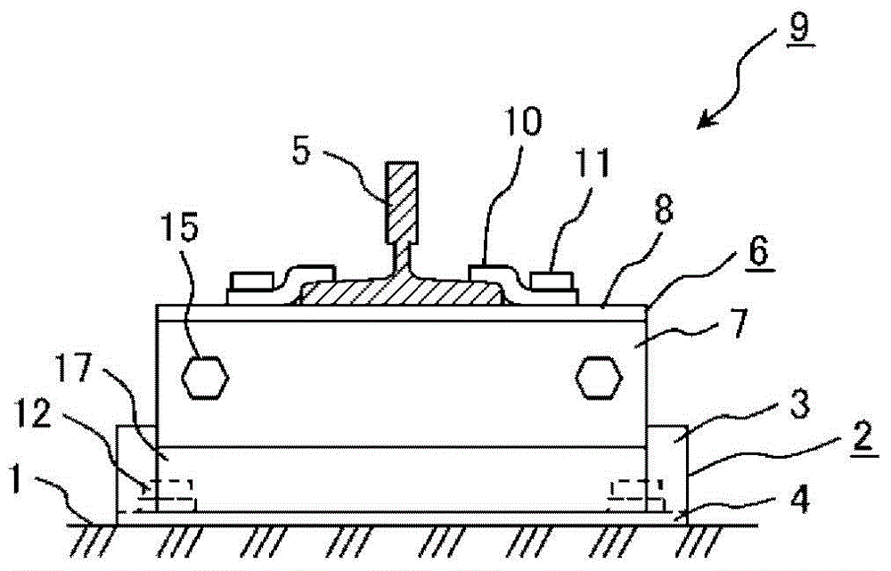
[0036] figure 1 is a side view showing the first embodiment of the present invention, figure 2 It is a plan view showing the first embodiment of the present invention. Such as figure 1 and figure 2 As shown, the first embodiment has a guide rail side bracket 6 for fixing the guide rail 5, a building side bracket 2, and a flat panel bracket 7 arranged between the two brackets.

[0037] The rail side bracket 6 has an L-shaped cross section and has a horizontal piece 7 and a vertical piece 8 . The vertical piece 8 has a through hole into which the bolt 11 is inserted. Two rail clamps 10 for fixing both ends of the rail 5 are fixed to the vertical piece 8 by bolts 11 as fasteners. The horizontal piece 7 has a threaded hole 23 that is threadedly fitted with a bolt 15 as a fastener.

[0038] The cross-section of the building side bracket 2 is L-shaped, and has a horizontal piece 3 and a vertical piece 4 . The building side support 2 has round holes on the vertical piece 4...

Embodiment 2

[0048] In Example 2, such as Figure 4 As shown, as the strength member 28 of the elevator passage, an intermediate beam or a fastening plate arranged on the wall of the elevator passage of the building is used to replace the building side bracket 2, and the flat support 17 is directly fixed on the strength member 28. According to the present invention, as described above, when using the intermediate beam and the fastening plate instead of the building side frame 2, although the degree of freedom of construction is slightly reduced, since there is no need to use new members, the cost of construction can be reduced.

Embodiment 3

[0050] In Example 3, such as Figure 5 As shown, a vise device 29 such as a vise is used instead of the bolt 15 for fixing the guide rail side bracket 6 , the elastic body 18 and the plate bracket 17 and for torque management of the compressive force borne by the elastic body 18 for fixing and torque management. Since the vise device 29 itself can display the tightening torque, torque management can be performed more conveniently. In the present invention, when the vise device 29 is used instead of the bolt 15, the same effect can be obtained.


PUM


Abstract

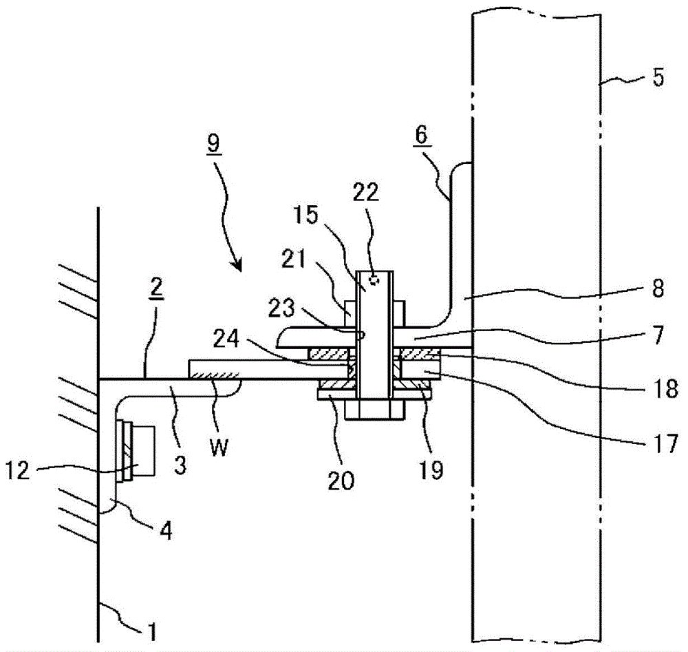
An elevator guide rail attaching device for attaching a guide rail inside a hoistway, wherein an elastic body (18) is held between a flat bracket (17) fixed to a hoistway wall (1) and a rail side bracket (6), and is secured in place using a fastener (15). In the device for attaching an elevator guide rail, this configuration allows torque to be controlled at a torque value that has a pronounced anti-vibration effect independent of the fastening torque between the guide rail and a rail clip. Furthermore, the components can be fixed by welding even when using an elastic body with a low heat tolerance.

Description

technical field [0001] The invention relates to a guide rail installation device of an elevator, which can reduce the vibration of the guide rail and the transmission of noise to the building side generated when the elevator is running. Background technique [0002] In a usual elevator, such as Figure 6 As shown, the hoist 27 is used to drive the elevator car 25 and the counterweight 26 in the hoistway of the building to make it lift. At this time, in order for the elevator car 25 and the counterweight 26 to move up and down smoothly, both are guided by the guide rail 5 . and, if Figure 7 and Figure 8 Shown, be provided with the guide rail support 9 that guide rail 5 is fixed on the building. [0003] The guide rail support 9 is composed of a building side support 2 with an L-shaped cross section and a guide rail side support 6 with an L-shaped cross section. The building side support 2 is fixed on the wall 1 of the lifting passage through the anchor bolts 12, and the ...

Claims


Application Information

Patent Timeline
Patent Type & Authority Applications(China)
IPC IPC(8): B66B7/02
CPCB66B7/024
Inventor 德野贵士大槻淳关谷裕二牛村真人
Owner HITACHI LTD
Learn More