
Moving object segmentation method based on optical flow field clustering

An optical flow field and motion technology, applied in image analysis, image data processing, instruments, etc., can solve problems such as high computational cost, difficulty in obtaining moving targets, and difficulty in detecting moving targets

Inactive Publication Date: 2014-11-19
HARBIN DIANSHI SIMULATION SCI & TECH
View PDF2 Cites 24 Cited by
  • Summary
  • Abstract
  • Description
  • Claims
  • Application Information

AI Technical Summary

Problems solved by technology

Under the condition of camera movement, especially when the scene is very complex, it is difficult to detect a complete moving target only by a single detection algorithm
For the case of multiple moving objects, the detection of moving objects becomes more complicated.
[0003] The previous method [1] (see Thompson W. B, Pong T. C. Detecting moving object. Int. J. Comp. Vision, 1990, 4: 39~57) was determined by using the optical flow direction of the moving object and the inner epipolar line constraint of the movement However, in a more complex natural background, it is difficult to obtain a complete moving target only by using the inner epipolar line constraints.
[0004] The previous method [2] (see Sasa G., Loncaric S. Spatio temporal image segmentation using optical flow and clustering algorithm. First Int'l workshop on image and signal processing and analysis, Pula, Croatia: 2000, 63~68) proposed A method of object segmentation using optical flow field motion information is proposed, but it is only applied to the case of simple background and static camera.
[0005] The previous method [3] (see Adiv G.. Determining three Dimensional motion and structure from optical flow generated by several moving objects. IEEE Trans, 1985, PAMI-7(4):384-401) by using the six parameters to complete the segmentation of the optical flow field of multiple moving objects, but the calculation cost of this segmentation is quite large.

Method used


Image

  • Moving object segmentation method based on optical flow field clustering
  • Moving object segmentation method based on optical flow field clustering
  • Moving object segmentation method based on optical flow field clustering

Examples


Embodiment Construction

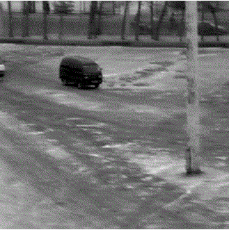
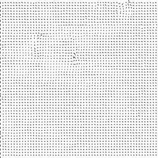
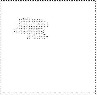
[0064] This embodiment combines Figure 1-12 The present invention is described in detail:

[0065] 1. Segment the optical flow field to form a segmentation map. Consider a camera moving relative to a fixed scene, and image the scene on the image plane through perspective projection. If the coordinate system is fixed to the camera, the scene can be considered to be moving relative to the camera. Yes, the motion of the scene can be described by the flow velocity of the image plane. At this time, the velocity is a function of the pixel coordinates of the object surface projected to the image plane, the motion of the camera relative to the object surface, and the distance between the camera and the object surface, described by formula (1)

[0066] (1)

[0067] (2)

[0068] (3)

[0069] In the formula, are in image pixel coordinates the flow velocity at has been normalized by the focal length, is the translation component, w...


PUM


Abstract

The invention discloses a moving object segmentation method based on optical flow field clustering. The method is characterized in that optical flow fields of an image sequence are clustered to effectively detect and segment single or multiple moving object(s) in a complex image background. An object area is segmented by utilizing moving internal epipolar constraint and C-mean value cluster algorithm to obtain a segmentation image; a detailed target area is obtained from the segmentation image by utilizing a Canny edge operator, and an edge image is obtained; and the segmentation image is merged with the edge image according to the flow velocity in the optical flow field, and complete single or multiple moving objects is / are detected. Thus, the moving object can be reliably segmented and detected under the condition that a camera moves.

Description

technical field [0001] The present invention is related to computer graphics and image understanding. In the case of camera movement, the background of the image sequence is very complex, which brings challenges to the detection and segmentation of the target. The present invention relates to a solution to the complex background conditions. A segmentation method for moving objects, using optical flow field clustering to achieve reliable detection of single and multiple objects. Background technique [0002] Moving object detection has always been a very important research content in the fields of machine vision, image understanding and computer graphics. Under the condition of camera movement, especially when the scene is very complex, it is difficult to detect a complete moving target only by a single detection algorithm. For the case of multiple moving objects, the detection of moving objects becomes more complicated. [0003] The previous method [1] (see Thompson ...

Claims


Application Information

Patent Timeline
IPC IPC(8): G06T7/00G06T7/20
Inventor 张泽旭王纲
Owner HARBIN DIANSHI SIMULATION SCI & TECH
Learn More