Bidirectional direct-current converter
A bidirectional DC conversion and DC terminal technology, applied in the field of converters, can solve the problems of affecting the transmission efficiency of the transformer and increasing the current of the switching element of the bridge arm, so as to achieve the effect of improving the efficiency of the transformer, limiting the voltage peak, and reducing the leakage inductance of the transformer
- Summary
- Abstract
- Description
- Claims
- Application Information
AI Technical Summary
Problems solved by technology
Method used
Image
Examples
Embodiment 1
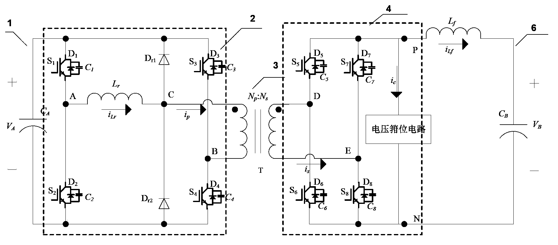
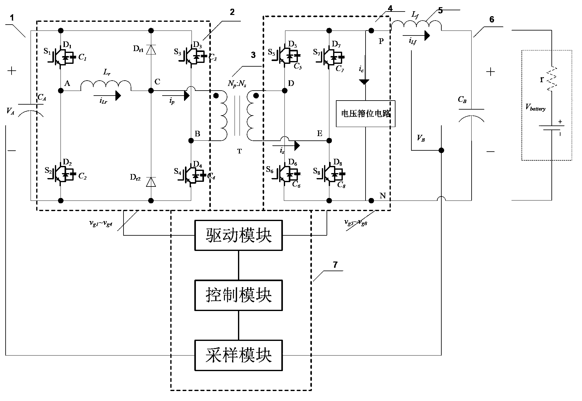
[0044] The following will refer to Figure 2-Figure 39 A first embodiment of the present application is described.
[0045] figure 2 A circuit diagram of a bidirectional DC converter according to the first embodiment of the present application is shown.
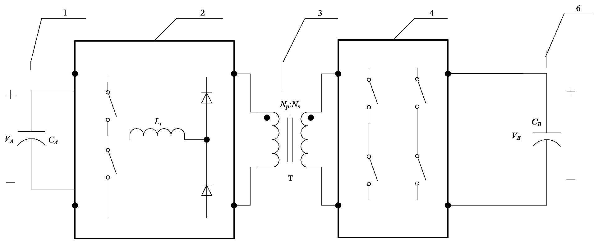
[0046] In the first embodiment of the present application, the bidirectional DC converter includes a primary side DC terminal 1, a primary side inverter / rectification module 2, an isolation transformer 3, a secondary side rectification / inversion module 4, and a secondary side DC terminal 6 .
[0047] Such as figure 2 As shown, the primary-side inverter / rectifier module 2 includes a first bridge arm and a clamping circuit. The first bridge arm consists of switching elements connected in series S 1 and S 2 Composed of, and through the high-voltage terminal capacitor C in parallel with it A Receive the voltage V of the DC terminal of the primary side A . The clamping circuit consists of a resonant inductor Lr and a se...
Embodiment 2
[0144] In the first embodiment, it is described that the two-terminal lagging arm of the isolation transformer located on the primary side (that is, the switching element S in the primary side inverter / rectifier module 1 and S 2 The working state of the circuit structure composed of the first bridge arm). In the second embodiment of the present application, the isolation transformer can also be connected to the super forearm, and the circuit structure is as follows Figure 40 shown. The circuit connection relationship in the bidirectional DC converter in this embodiment and figure 2 The first embodiment shown is basically the same, except that the first bridge arm is composed of switching elements S connected in series 3 and S 4 Composed of, the second bridge arm is composed of switching elements S connected in series 1 and S 2 Composed, and the second bridge arm is coupled to the two ends of the isolation transformer T on the primary side as the leading bridge arm. Si...
Embodiment 3
[0182] Figure 43 A circuit structure diagram of a bidirectional DC converter according to the third embodiment of the present application is shown. like Figure 43 As shown, except for the primary-side inverter / rectifier module, the circuit structure of the bidirectional DC converter of this embodiment is the same as figure 2 The bidirectional DC converter shown is basically the same. In this embodiment, the primary-side inverter / rectifier module includes figure 2 In addition to the first bridge arm and the clamping circuit shown in , it also includes a capacitor C connected in series 3 and C 4 composed of capacitive bridge arms. The capacitor bridge arm, the first bridge arm and the clamping bridge arm are connected in parallel to the DC terminal 1 of the primary side, one end of the winding on the primary side of the transformer is connected to the midpoint C of the clamping bridge arm, and the other end is connected to the capacitor bridge arm midpoint B of .
[0...
PUM
 Abstract
Description
Claims
Application Information
 - R&D
- Intellectual Property
- Life Sciences
- Materials
- Tech Scout
- Unparalleled Data Quality
- Higher Quality Content
- 60% Fewer Hallucinations
Browse by: Latest US Patents, China's latest patents, Technical Efficacy Thesaurus, Application Domain, Technology Topic, Popular Technical Reports.
© 2025 PatSnap. All rights reserved.Legal|Privacy policy|Modern Slavery Act Transparency Statement|Sitemap|About US| Contact US: help@patsnap.com


