Ultra-thin combined transformer

A combined transformer, ultra-thin technology, applied in the field of transformers, can solve the problems of not conforming to the development trend of small volume and high power, incomplete coupling of primary and secondary windings, inability to use automatic winding, etc., to meet the requirements of light, thin and small design, improve Production efficiency and the effect of improving the utilization of magnetic cores

Active Publication Date: 2016-05-04
江苏晨朗电子集团有限公司
View PDF4 Cites 1 Cited by
  • Summary
  • Abstract
  • Description
  • Claims
  • Application Information

AI Technical Summary

Problems solved by technology

[0003] However, the design cost of implementing safety regulations by means of barrier wall and three-layer insulated wire isolation and left and right isolation is relatively high, the process is cumbersome, and automatic winding cannot be used because the barrier wall needs to be wound manually, and the production efficiency is low; while left and right isolation The design method makes the coupling of the primary and secondary windings incomplete, the utilization rate of the magnetic core is not high, and it does not conform to the development trend of small volume and high power

Method used


Image

  • Ultra-thin combined transformer
  • Ultra-thin combined transformer
  • Ultra-thin combined transformer

Examples


Embodiment Construction

[0016] Below in conjunction with accompanying drawing, the present invention will be further described:

[0017] Please refer to figure 1 , figure 1 It is a schematic diagram of the assembly structure of the ultra-thin combined transformer of the present invention.

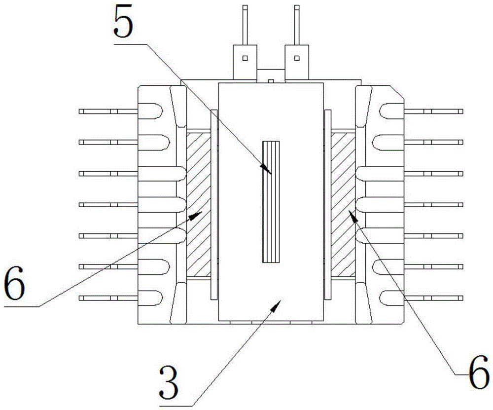
[0018] An ultra-thin combined transformer, comprising a winding frame 1 and a packaging frame, the winding frame 1 is arranged in the packaging frame, and the winding frame 1 has three parallel winding slots 4, in the middle A primary coil 5 is wound in the winding slot 4 , and a secondary coil 6 is wound in the winding slot 4 on both sides.

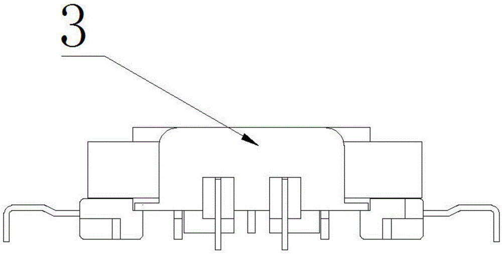
[0019] Such as figure 2 with image 3 as shown, figure 2 It is a schematic view of the structure of the ultra-thin combined transformer of the present invention, image 3 It is a schematic diagram of the side structure of the ultra-thin combined transformer of the present invention.

[0020] The lower surface of the winding frame 1 is provided with a wire-entry groo...


PUM


Abstract

The invention provides an ultrathin combined type transformer which comprises a coil winding framework and an encapsulating frame, wherein the coil winding framework is arranged in the encapsulating frame; three parallel coil winding slots are arranged on the coil winding framework; a primary coil is wound in the middle coil winding slot; and a secondary coil is wound in each of the coil winding slots at the two sides. The ultrathin combined type transformer disclosed by the invention is small in size, and formed by assembling and combining a flat magnetic core structure with the coil winding framework, so that a mode of isolating by adopting a retaining wall adhesive tape is abandoned; a mode of isolating by adopting a slot separating structure of the coil winding framework is adopted, and an automatic coil winding machine is adopted for winding, so that the production efficiency is improved; a mode of winding the primary coil on the middle coil winding slot and winding the secondary coils on the coil winding slots at the two sides is adopted to strengthen primary-secondary coil coupling, design with a great ratio of winding is adopted to improve a magnetic core utilization rate, so that power raising is realized; a bend-pin sinking plate is adopted on a plate-pasting encapsulating structure, and a PCB is holed, so that the transformer body is sunken to effectively dissipate the heat; and the height of the transformer is lowered by utilizing the thickness of the PCB body structure, so that thin and small design requirements are met.

Description

technical field [0001] The invention relates to a transformer, in particular to a sunken plate combined switching power supply transformer. Background technique [0002] Currently, switching power supply transformers used in LED TVs have safety isolation requirements due to high voltage. Usually, the design adopts the combination of safety tape retaining wall and three-layer insulated wire to isolate or adopts the structure of the left and right sides of the winding skeleton body to isolate the input and output to achieve the electrical distance and creepage distance requirements required by safety standards. [0003] However, the design cost of implementing safety regulations by means of barrier wall and three-layer insulated wire isolation and left and right isolation is high, the process is cumbersome, and automatic winding cannot be used because the barrier wall needs to be wound manually, and the production efficiency is low; while the left and right isolation The desi...

Claims


Application Information

Patent Timeline
Patent Type & Authority Patents(China)
IPC IPC(8): H01F27/30
Inventor 陈栋管宏胜
Owner 江苏晨朗电子集团有限公司
Why Eureka
Try Eureka