
Camera module

A technology of camera module and fixed part, applied in image communication, television, camera and other directions, can solve the problems of difficult realization of small digital camera module and inability to realize optical zooming and so on

Inactive Publication Date: 2014-11-12
OPTIS
View PDF5 Cites 13 Cited by
  • Summary
  • Abstract
  • Description
  • Claims
  • Application Information

AI Technical Summary

Problems solved by technology

Therefore, the function of optical zoom cannot be realized. The image sensor and image processing chip enlarge and process the electrical signal related to the optical image, which is the so-called "digital zoom" function to adjust the magnification of the lens group.
[0004] Although the autofocus function or optical zoom (zoom) function is very common in existing digital cameras, it is still difficult to implement on small digital camera modules whose vertical and horizontal sizes are reduced to within a few 10mm

Method used


Image

  • Camera module
  • Camera module
  • Camera module

Examples


Embodiment Construction

[0028] Embodiments according to the present invention will be described in detail below with reference to the accompanying drawings. In this process, the size, shape, etc. of the components shown in the drawings may be exaggerated for clear and simple explanation. In addition, the terms specifically defined in consideration of the configuration and operation of the present invention may vary depending on the user's or operator's intention or practice. Definitions of these terms should be determined based on the overall content of this specification.

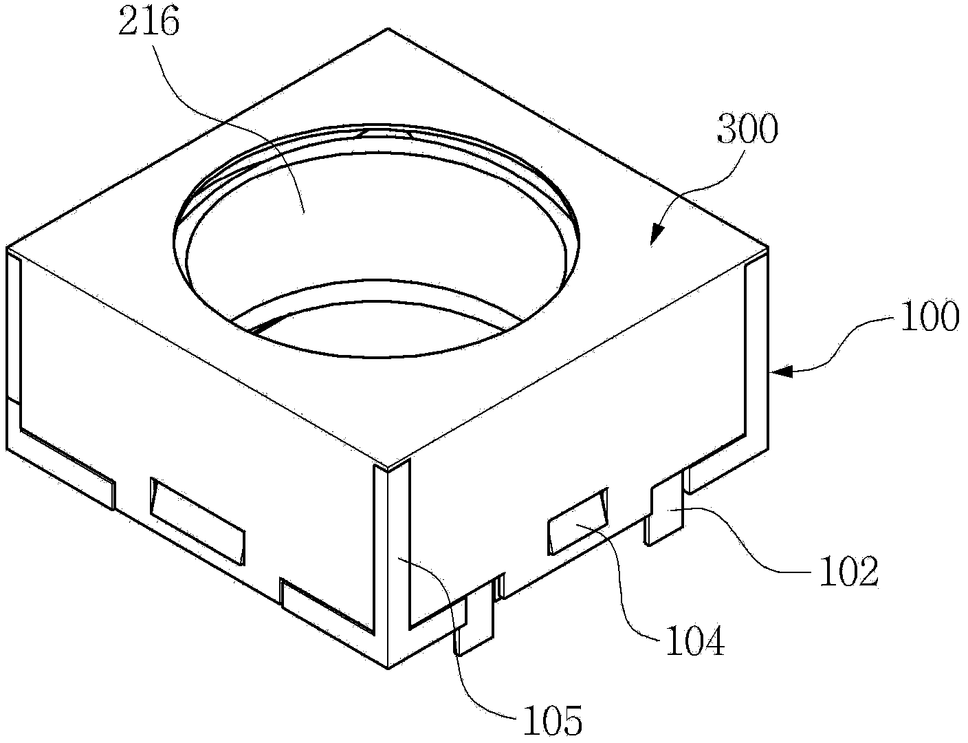
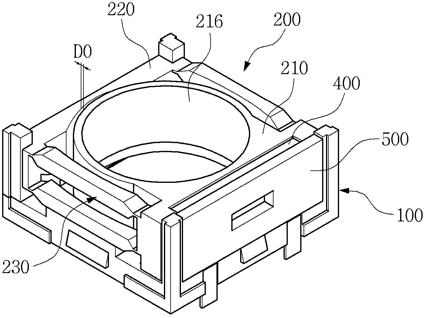
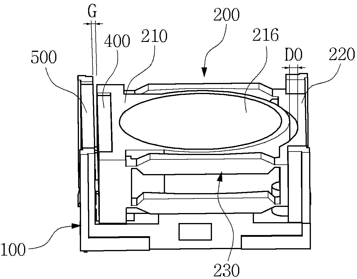
[0029] figure 1 It is an oblique view of the appearance of the camera module of the present invention. figure 2 It is a partial oblique view showing the inside of the camera module of the present invention after removing the cover. image 3 With figure 2 Partial oblique views of different sight lines. Figure 4 It is an exploded oblique view of the camera module of the present invention. Figure 5 It is a side view briefl...


PUM


Abstract

Disclosed herein is a camera module. The camera module includes a bobbin unit, a suspension unit and a drive unit. The bobbin unit includes a stationary part which is fixed in a base, and a movable part which is provided so as to be movable relative to the stationary part, with a lens installed in the movable part. The opposite ends of the suspension unit are respectively connected to the stationary part and the movable part. The suspension unit includes a link unit which rotates when the movable part moves relative to the stationary part. The drive unit moves the movable part relative to the stationary part.

Description

technical field [0001] The invention relates to a camera module with a moving lens. Background technique [0002] The mobile phone has a built-in high-resolution small camera module with several million pixels. A unique compact digital camera module with high resolution. Although it is small in size, it must have the function of auto focusing or optical zoom (zoom) in order to achieve precise image quality. [0003] In order to reduce the manufacturing cost or the size of the product in the existing low-pixel camera module, the lens group is fixed in the direction of the optical axis. Therefore, the function of optical zoom cannot be realized, and the image sensor and image processing chip enlarge and process the electrical signal related to the optical image, that is, the so-called 'digital zoom' function to adjust the magnification of the lens group. [0004] Although the autofocus function or optical zoom (zoom) function is very common in existing digital cameras, it is...

Claims


Application Information

Patent Timeline
Patent Type & Authority Applications(China)
IPC IPC(8): G03B17/12G03B13/32G02B7/04
CPCG03B13/32G03B17/12H04N5/2251G02B7/08G02B7/04G03B3/10G02B7/09H04N5/2254G03B5/04G02B7/026G03B13/36H04N5/23241H04N5/2257G03B2205/0015G03B2205/0046G03B2205/0069H04N23/57H04N23/55H04N23/651
Inventor 李周炯申景湜金珍琪金钟烈
Owner OPTIS
Learn More