Method for analyzing pre-stack time migration response of seismological observation system

A seismic observation system, pre-stack time migration technology, applied in the direction of seismic signal processing, etc., can solve the problems of not considering the influence of seismic noise, low analysis accuracy, poor three-dimensional analysis ability of imaging quality, etc.

Active Publication Date: 2014-11-12
CHINA PETROLEUM & CHEM CORP +1
View PDF5 Cites 10 Cited by
  • Summary
  • Abstract
  • Description
  • Claims
  • Application Information

AI Technical Summary

Problems solved by technology
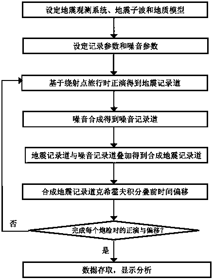
[0005] The present invention aims to overcome the problems of poor three-dimensional analysis of imaging quality, lack of consideration of seismic noise, and low analysis precision in the prior art, and provides an analysis method for pre-stack time migration response of seismic observation system

Method used


Image

  • Method for analyzing pre-stack time migration response of seismological observation system
  • Method for analyzing pre-stack time migration response of seismological observation system
  • Method for analyzing pre-stack time migration response of seismological observation system

Examples


Embodiment 2

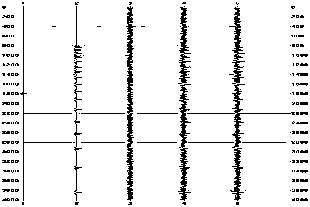
[0066] Example 2: The set parameters of observation system 2 are: 8-line receiving, 100 lines / receiving line, track distance 50 meters, receiving line distance 200 meters, number of shots in the beam 4, shot distance 50 meters, shot line distance 200 meters, the rolling distance between beams is 200 meters. According to the steps described in Example 1, the obtained pre-stack time migration response is as follows Figure 7 and Figure 8 shown, Figure 7 and Figure 5 There is little difference between the two, but Figure 8 and Image 6 By comparison, it can be seen that Figure 8 The middle side lobe noise is obviously smaller, and the range of 8 channels is higher than that of Image 6 The mid-side lobe noise has a small range and a small background noise, indicating that the imaging quality of observation system 1 and observation system 2 in the inline direction is comparable, but observation system 2 is beneficial to obtain better imaging results in the crossline dir...

Embodiment 3

[0067] Example 3: The set parameters of observation system 3 are: 32 lines of receiving, 100 lines / receiving line, track distance of 50 meters, receiving line distance of 100 meters, number of shot points in the beam 10, shot point distance of 80 meters, and shot line distance 80 meters, rolling distance between beams is 800 meters; geological models such as Figure 9 Shown is a complex fault block geological model. According to the steps described in Example 1, the obtained Figure 10 The inline-direction prestack time migration response of observation system 1 is shown and Figure 11 The inline direction prestack time migration response of observation system 3 is shown. Figure 11 and Figure 10 The comparative analysis shows that the observation system 1 can achieve reliable imaging of complex fault blocks, but the noise on the response profile of the pre-stack time migration is relatively strong, which indicates that the observation system 1 still lacks the ability to s...


PUM


Abstract

The invention relates to a method for analyzing the pre-stack time migration response of a seismological observation system. For the given seismological observation system, a geologic model and seismic noise parameters, a seismic record cannel is obtained through the forward modelling method obtained when a diffraction point travels aiming at each shot point-demodulator point pair in the seismological observation system, a noise recording channel is obtained through synthesis according to the noise parameters, a synthetic seismic record channel is obtained through superposition of the seismic record cannel and the noise recording channel, a pre-stack time migration result is obtained through Kirchhoff pre-stack time migration by the synthetic seismic record channel, superposition is conducted on the pre-stack time migration results of all the shot points-demodulator points in the seismological observation system to obtain the pre-stack time migration response of the seismological observation system, and the response is represented by a seismic cross-section graph to be used for evaluating the imaging effect of pre-stack time migration of the seismological observation system.

Description

Technical field: [0001] The invention relates to an analysis method for the pre-stack time migration response of a seismic observation system, which is used for evaluating the imaging effect of the pre-stack migration of the seismic observation system, and belongs to the field of seismic exploration and acquisition design. Background technique: [0002] In the current 3D seismic exploration, the design of the seismic observation system is mainly based on the demonstration of basic parameters, and several schemes are designed according to past experience, and then the final seismic observation system scheme is evaluated and selected by using the coverage times and offset distributions and other graphs. These seismic observation system evaluation methods cannot directly reflect the imaging effect of prestack time migration, and can no longer meet the requirements of prestack time migration processing technology. [0003] Li Peiming et al. (application number: 201110043602.1) o...

Claims


Application Information

Patent Timeline
Patent Type & Authority Applications(China)
IPC IPC(8): G01V1/30
Inventor 秦广胜蔡其新汪功怀肖斌武正伦张建章魏长洲赵洪豪
Owner CHINA PETROLEUM & CHEM CORP
Why Eureka
Try Eureka