
Electrode component for ultra-high-performance projection lamp and manufacturing method thereof

An electrode assembly, ultra-high-performance technology, applied in the direction of manufacturing tools, projection devices, instruments, etc., can solve the problems of solder joints falling off, long welding time, and uneven discharge on the electrode surface, so as to increase the welding area and achieve good welding consistency , low wear and deformation effect

Inactive Publication Date: 2014-11-12
上海亚尔光源有限公司
View PDF7 Cites 0 Cited by
  • Summary
  • Abstract
  • Description
  • Claims
  • Application Information

AI Technical Summary

Problems solved by technology

Due to the thicker diameter of the tungsten rod, the current cannot flow evenly through the two contact surfaces, which makes it difficult to guarantee the quality of the welded product, and the consistency of the welding strength is very poor. The specific disadvantages are as follows:
[0003] (1) Welding tungsten rod with a diameter of 0.8mm or more and using resistance welding cannot ensure that the weldment is completely melted, resulting in very unstable welding strength
[0004] (2) The surface of the electrode is uneven due to discharge, which requires a lot of manual grinding work
And useless electrodes will cause pollution after being discarded
[0005] (3) After the subsequent hydrogen burning treatment, the solder joints will fall off
[0006] (4) During welding, since the tungsten rod is extremely thick compared to the molybdenum sheet, and the molybdenum sheet material is extremely thin (0.02mm), the extrusion of the upper and lower electrodes will cause the deformation of the product
[0007] (5) Changes in welding energy, resulting in brittle products and over-welding
[0008] (6) Manual welding of products, long welding time for a single product, and low labor efficiency
The welding size requirements are high, and the quality of welding cannot be guaranteed by using simple fixtures

Method used


Image

  • Electrode component for ultra-high-performance projection lamp and manufacturing method thereof
  • Electrode component for ultra-high-performance projection lamp and manufacturing method thereof

Examples


Embodiment

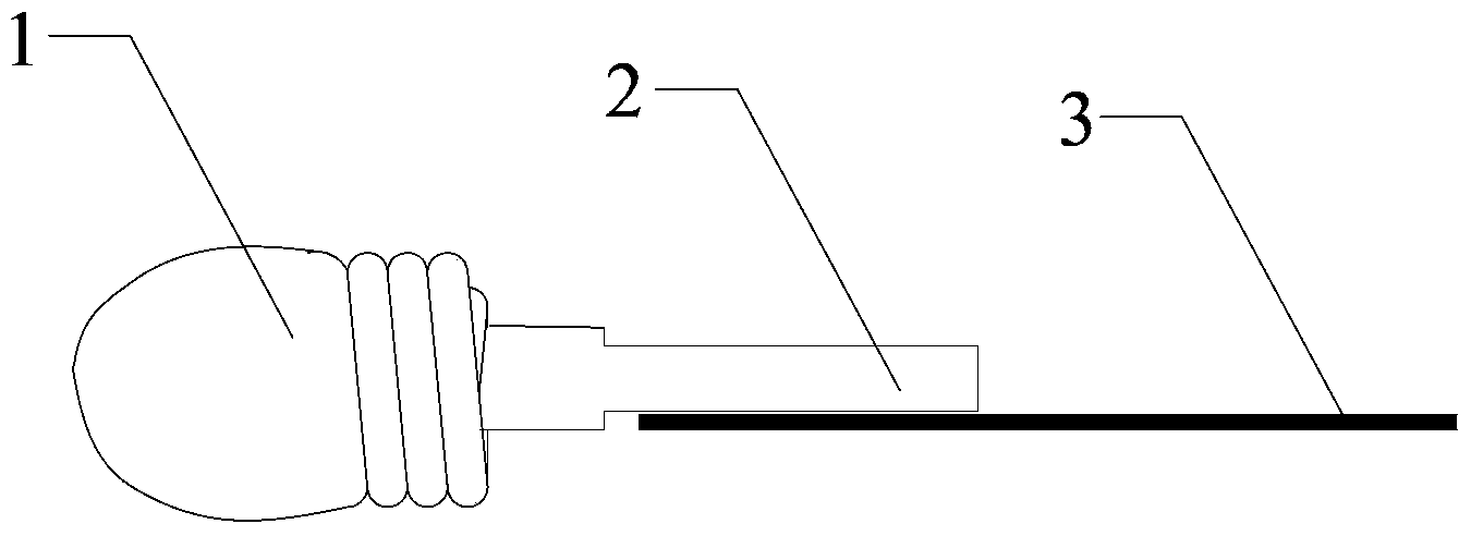
[0035] An electrode assembly for an ultra-high performance projection lamp, the structure of which is as figure 1 As shown, the electrode assembly is welded by an electrode 1 and a molybdenum sheet 3. The end of the electrode 1 is provided with a flat tungsten rod 2. The width of the tungsten rod 2 is 0.8-2.5 mm. The sheet 3 is connected by laser welding, and the weld seam of the laser welding is located at the center line of the flat tungsten rod 2 .

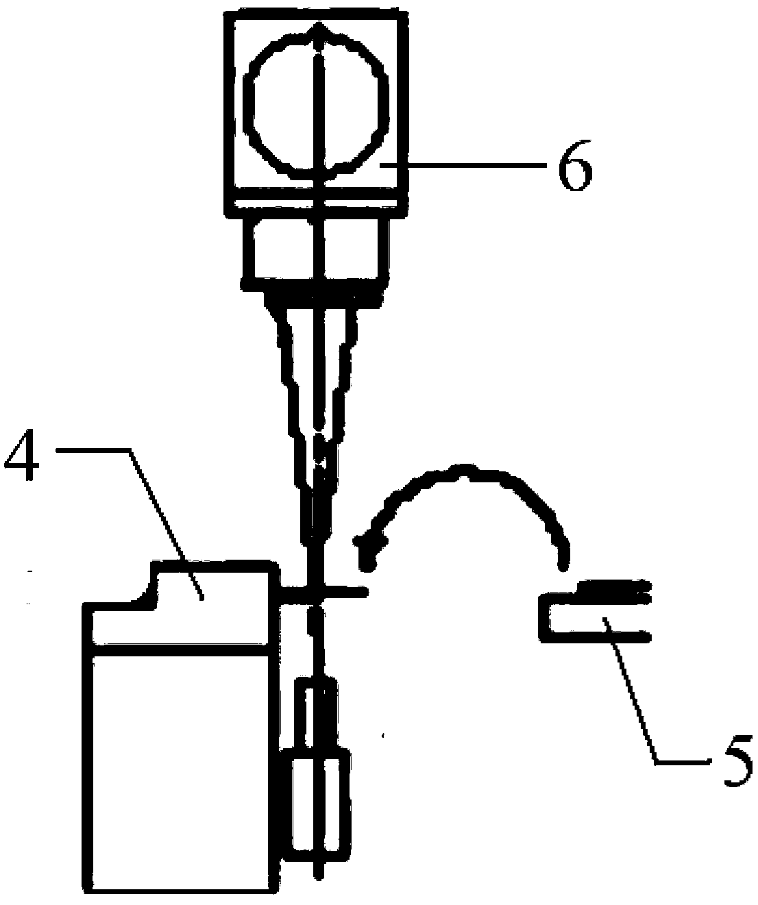
[0036] During manufacture, the molybdenum sheet 3 is fixed by the molybdenum sheet fixture 4, the tungsten rod 2 provided at the end of the electrode 1 is fixed by the tungsten rod jig 5, and then the laser generated by the laser generator is output through the laser output head 6, and the electrode and the molybdenum Sheet 3 is soldered to the connection. Among them, the laser generates a 1-8KW continuous single-wavelength beam from the yttrium aluminum garnet crystal rod (Nd:YAG) in which neodymium (ND) is the excitation ele...


PUM

PropertyMeasurementUnit
Widthaaaaaaaaaa
Wavelengthaaaaaaaaaa

Abstract

The invention relates to an electrode component for an ultra-high-performance projection lamp and a manufacturing method of the electrode component. The electrode component is formed by a welding electrode and a molybdenum plate. The electrode and the molybdenum plate are connected through laser welding, a flat tungsten rod is arranged at the tail end of the electrode, the molybdenum plate is fixed through a molybdenum plate clamp, the tungsten rod at the tail end of the electrode is fixed through a tungsten rod jig, then, laser generated by a laser generator is output through a laser emergent head, and the electrode is in welding connection with the molybdenum plate. Compared with the prior art, the problem that laser welding cannot be carried out on a high-power electrode is solved, the laser energy is controlled to be stable, flattened treatment is carried out on the surface of the tungsten rod, the welding area is added, it is ensured that the molybdenum plate cannot be prone to being punched, the product welding consistency is good, and the quality is ensured.

Description

technical field [0001] The invention relates to an electrode assembly and a manufacturing method thereof, in particular to an electrode assembly for an ultra-high performance projection lamp and a manufacturing method thereof. Background technique [0002] The strength of ultra-high-performance projection lamp welding has always been one of the problems that plague lighting electrode manufacturers. The existing technology uses discharge welding of upper and lower tungsten electrodes, that is, the thick tungsten rod and molybdenum sheet are pressed between the two electrodes, and a current is applied. It is a method of heating it to a molten or plastic state by using the resistance heating effect generated by the current flowing through the contact surface of the workpiece and the adjacent area to form a metal bond. Due to the thicker diameter of the tungsten rod, the current cannot flow evenly through the two contact surfaces, which makes it difficult to guarantee the qualit...

Claims


Application Information

Patent Timeline
IPC IPC(8): B23K26/24G03B21/14
CPCB23K26/24
Inventor 何健荣刘宏胡欣
Owner 上海亚尔光源有限公司
Learn More