
Frequency calibration circuit and method thereof

A frequency calibration and circuit technology, applied in the direction of electrical components, automatic power control, etc., can solve the problems of low accuracy and slow frequency calibration technology, and achieve the effect of improving sampling accuracy, fast and high-precision frequency calibration, and avoiding loss of lock.

Inactive Publication Date: 2014-11-05
SHANGHAI JIAO TONG UNIV
View PDF5 Cites 29 Cited by
  • Summary
  • Abstract
  • Description
  • Claims
  • Application Information

AI Technical Summary

Problems solved by technology

[0009] In view of the shortcomings of the prior art described above, the purpose of the present invention is to provide a frequency calibration circuit and its method, which are used to solve the problems of slow speed and low precision of the frequency calibration technology in the prior art.

Method used


Image

  • Frequency calibration circuit and method thereof
  • Frequency calibration circuit and method thereof
  • Frequency calibration circuit and method thereof

Examples


Embodiment Construction

[0090] Embodiments of the present invention are described below through specific examples, and those skilled in the art can easily understand other advantages and effects of the present invention from the content disclosed in this specification. The present invention can also be implemented or applied through other different specific implementation modes, and various modifications or changes can be made to the details in this specification based on different viewpoints and applications without departing from the spirit of the present invention.

[0091] see Figure 1 to Figure 7 . It should be noted that the diagrams provided in this embodiment are only schematically illustrating the basic idea of ​​the present invention, and only the components related to the present invention are shown in the diagrams rather than the number, shape and shape of the components in actual implementation. Dimensional drawing, the type, quantity and proportion of each component can be changed arb...


PUM


Abstract

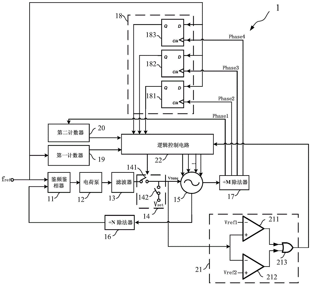
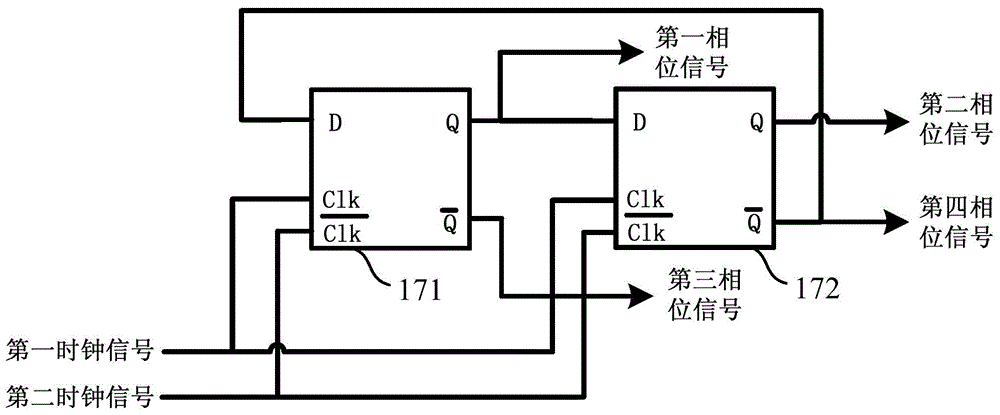
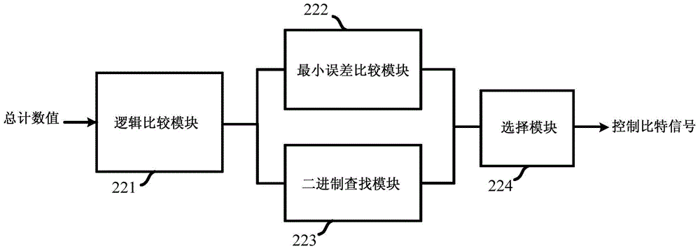
The invention provides a frequency calibration circuit and a method thereof. The frequency calibration circuit comprises a phase lock loop circuit, an M-dividing divider for generating a plurality of phase signals, a sampling circuit for sampling on the rising edges of the phase signals, a first counter for counting reference frequency signals, a second counter counting first phase signals, a logical control circuit for comparing a count value with a target count value to obtain a minimum difference value, and looking up a control bit of a voltage-controlled oscillator through the difference value, and a comparison circuit for judging whether the control voltage of the voltage-controlled oscillator is in a set range or not. The method comprises the following steps: sampling the reference frequency signals to obtain a total count value; comparing the total count value with a target count value; selecting a next resonance line according to a binary lookup flow till binary lookup ends; and outputting a resonance line corresponding to a minimum error in order that the output frequency of the voltage-controlled oscillator reaches a required value. Through adoption of the frequency calibration circuit and the method thereof, the speed and accuracy are increased, and the requirement on the working frequency of a digital circuit is lowered, so that a design method is simplified.

Description

technical field [0001] The invention relates to the field of integrated circuits, in particular to a frequency calibration circuit and a method thereof. Background technique [0002] In the field of wireless communication, a phase-locked loop frequency synthesizer (Phase Lock Loop, PLL) is an essential part of a wireless transceiver chip. A phase-locked loop circuit generates a stable, low-phase-noise signal at a certain frequency. In modern wireless communication chips, due to the increasing number of wireless communication protocols, considering cost and market factors, wireless transceiver chips that support multiple frequency bands and multiple modes have become mainstream. Therefore, the phase-locked loop module needs to support multi-band output. Since multiple phase-locked loops will inevitably bring about problems of power consumption and excessive area, a broadband single phase-locked loop circuit has become the mainstream of the market. [0003] In the phase-loc...

Claims


Application Information

Patent Timeline
Patent Type & Authority Applications(China)
IPC IPC(8): H03L7/18
Inventor 周阳阳严皓秦鹏周健军
Owner SHANGHAI JIAO TONG UNIV
Learn More