
Method for recognizing rotor crack fault of steam turbine generator unit

A technology for steam turbine generator set and rotor cracks, which is applied in the field of diagnosing crack faults and identifying rotor crack faults of steam turbine generator sets, and can solve problems that affect the accuracy of flaw detection results of flaw detection instruments, are difficult to detect on-site flaw detection, and affect the safe operation of units, etc. , to achieve the effect of preventing catastrophic accidents, avoiding huge economic losses, and avoiding deviations

Inactive Publication Date: 2014-11-05
XIAN THERMAL POWER RES INST CO LTD
View PDF4 Cites 7 Cited by
  • Summary
  • Abstract
  • Description
  • Claims
  • Application Information

AI Technical Summary

Problems solved by technology

However, if there is a crack inside the rotor, it is sometimes difficult to detect it on-site if it does not extend to the surface.
At the same time, due to the characteristics of the rotor structure of the unit, for example, it is limited by the shaft seal of the finished steam turbine rotor, the root of the blade, and the lower shaft of the fan ring of the generator rotor set, which may affect the accuracy of the flaw detection results of the flaw detection instrument on these parts, and sometimes it is impossible to detect. existing cracks
In addition, in some cases, the rotor crack develops very quickly, and the crack has developed to a dangerous level that seriously affects the safe operation of the unit before the unit is shut down for maintenance.

Method used


Image

  • Method for recognizing rotor crack fault of steam turbine generator unit
  • Method for recognizing rotor crack fault of steam turbine generator unit
  • Method for recognizing rotor crack fault of steam turbine generator unit

Examples


Embodiment 1

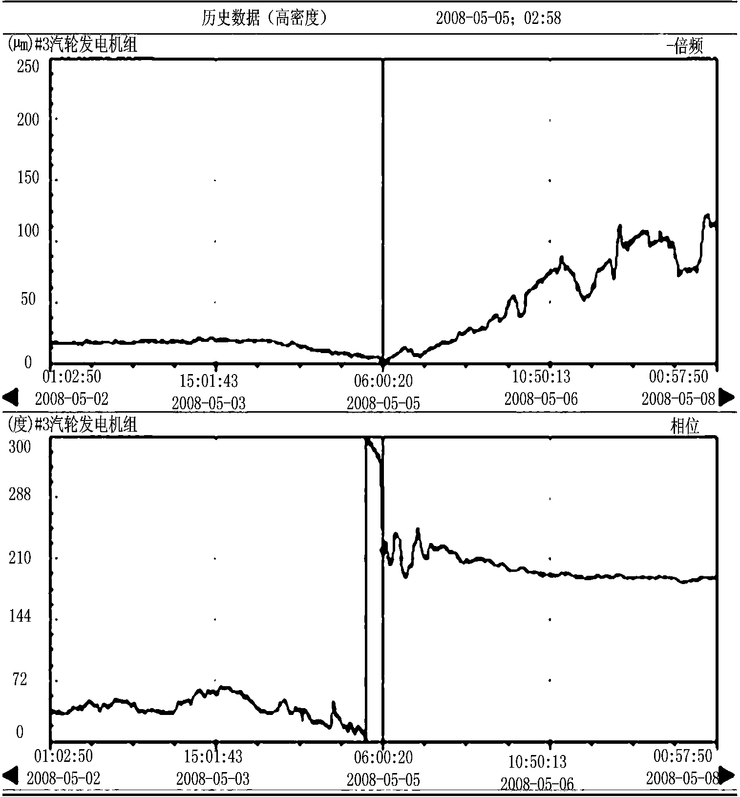
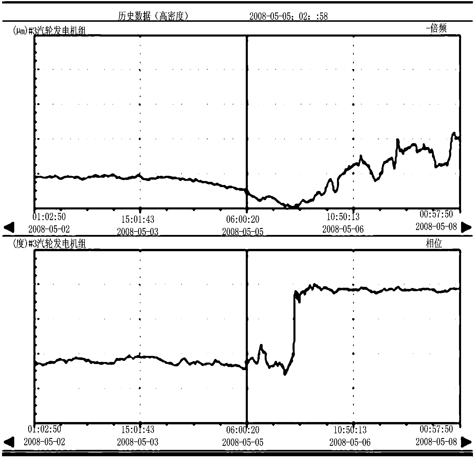
[0026] Since May 6, 2008 in a subcritical 600MW unit, the vibration of two bearings of the generator has climbed from the vibration trend. The vibration characteristics are as follows: (1) The vibration has nothing to do with the sealing oil temperature, hydrogen temperature and hydrogen pressure; (2) The vibration has nothing to do with the excitation current; (3) The vibration is related to the active load, the active load increases, the vibration increases, but even if the active load decreases, the vibration base continues to increase; (4) The vibration is mainly 1 times the frequency component ; (5) When the shaft vibration of No. 7 bearing and No. 8 bearing increases, the tile vibration also increases synchronously, but the shaft vibration and tile vibration of No. 6 bearing decrease; (6) When the vibration is at a high level, the controllable series compensation of the power grid exits During operation, the axial vibration of the No. 7 bearing in the X and Y directions d...

Embodiment 2

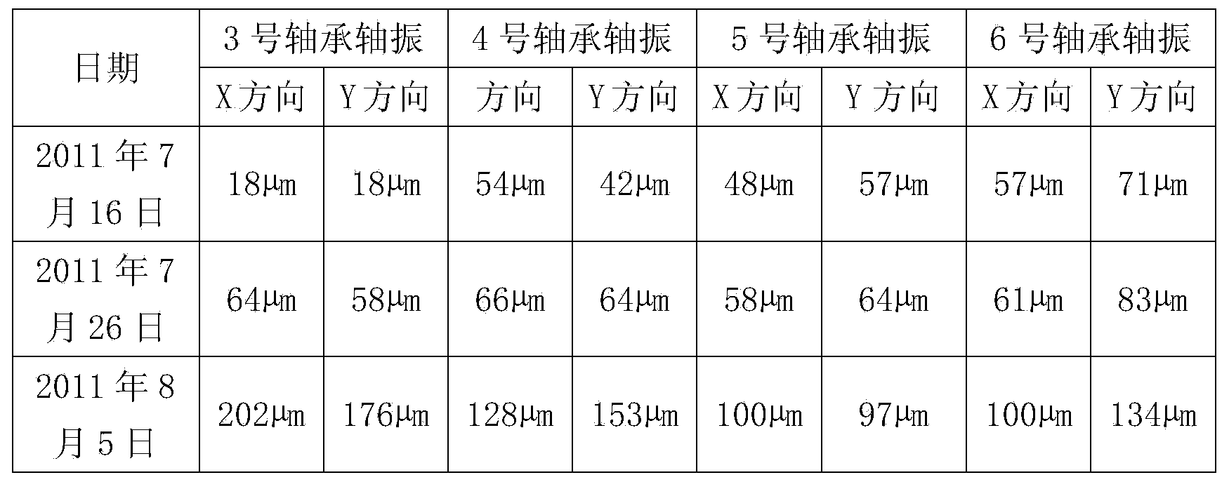
[0031] Referring to Table 1, the vibration of the two low-pressure rotors of a supercritical 660MW steam turbine has always been good. However, after July 18, 2011, it was found that the shaft vibration of the No. 3 bearing showed an increasing trend. Before the unit shut down on August 5, the maximum Shaft vibration has reached above 200μm.

[0032] Table 1

[0033]

[0034] The vibration of this unit is mainly in the 1-fold frequency component, and the vibration change is shown as a small increase in the shaft vibration of the No. The vibration exceeds 80μm, but when it passes near the low-pressure critical speed during shutdown, the shaft vibration of No. 3-6 bearings is very small, and the maximum does not exceed 75μm, and at low speed (about 300r / min) the journal of No. 3-6 bearings shakes The shaft vibration of the No. 3 bearing has a strong correlation with the steam seal system. When the desuperheating water is put in, the vibration will rise rapidly. In this case,...


PUM


Abstract

The invention discloses a method for recognizing a rotor crack fault of a steam turbine generator unit. The method comprises the steps that first, in the running process of the steam turbine generator unit, vibration characteristic components of a rotor in the steam turbine generator unit are measured in real time, wherein the vibration characteristic components of the rotor include the rotor vibration trend, the rotor vibration frequency spectrum and the rotor vibration phase position; second, whether a crack fault happens to the rotor of the steam turbine generator unit or not is judged according to the vibration characteristic components. Thus, early warnings about early-stage cracks of the rotor are achieved, an operation unit can be prompted to perform shutdown in time to perform flaw detection examination and handling, and the possible disastrous accident that a shaft is broken and a machine is destroyed due to continuous operation of the unit is avoided.

Description

technical field [0001] The invention belongs to the technical field of fault diagnosis of rotating mechanical equipment, and relates to a method for diagnosing crack faults, in particular to a method for identifying crack faults in the rotor of a steam turbine generator set. Background technique [0002] Rotor cracks are major faults that threaten the safe and stable operation of rotating machinery such as turbogenerators. If it is not discovered in time, when the rotor crack develops to the final stage, it will lead to a catastrophic shaft breaking accident during the operation of the unit, resulting in huge economic losses and bad social impact. The current method of detecting rotor cracks is usually to conduct ultrasonic, magnetic particle and infrared flaw detection inspections on the rotor during the overhaul of the unit. If cracks appear on the surface of the rotor, the existing cracks can generally be detected by these conventional flaw detection methods. However, i...

Claims


Application Information

Patent Timeline
Patent Type & Authority Applications(China)
IPC IPC(8): G01M13/00
Inventor 张学延何国安张卫军葛祥
Owner XIAN THERMAL POWER RES INST CO LTD
Learn More