Axial pressure type rust removing device for surface of petroleum drill rod

A technology of oil drill pipe and axial pressure, which is applied in the direction of grinding drive device, grinding workpiece support, grinding machine, etc., can solve the problems of high operating intensity, long construction period, and low efficiency of construction personnel, and achieve the goal of reducing labor intensity Effect

Inactive Publication Date: 2014-11-05
CHENGDU GAOPU PETROLEUM ENG TECH
View PDF5 Cites 3 Cited by
  • Summary
  • Abstract
  • Description
  • Claims
  • Application Information

AI Technical Summary

Problems solved by technology

[0002] After use, the surface of the oil drill pipe will form a dirt layer and rust layer. During equipment maintenance, the oil drill pipe needs to remove the dirt layer and rust layer on the surface. The operation of the prior art is to use a manual hand-held grinder for grinding. To remove the dirt layer and rust layer, this method has the following disadvantages: the construction period is long, the construction personnel’s operation intensity is high, and the efficiency is extremely low. It takes at least 3 days to remove an oil drill pipe, and other auxiliary equipment is needed to help rotate it. The construction environment of oil drill pipe is harsh. Due to the existence of petroleum substances and rust substances on the surface of the used oil drill pipe, when grinding, the high temperature and high-speed rotation will lift the rust dust into the air, and the construction workers will inhale the pollutants. , which is extremely harmful to construction workers

Method used


Image

  • Axial pressure type rust removing device for surface of petroleum drill rod
  • Axial pressure type rust removing device for surface of petroleum drill rod
  • Axial pressure type rust removing device for surface of petroleum drill rod

Examples


Embodiment 1

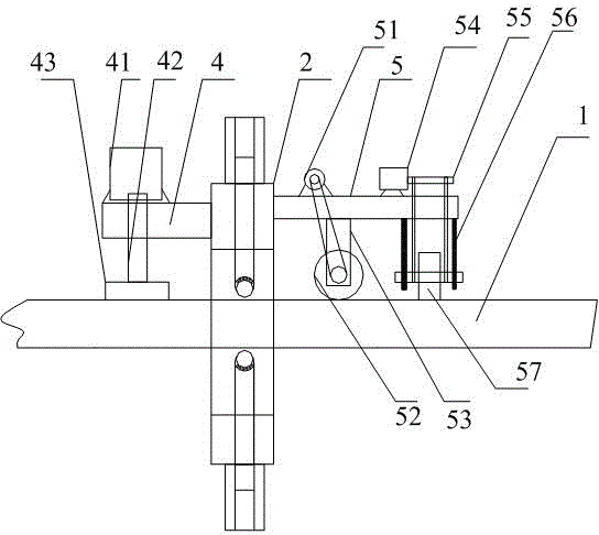
[0022] Such as Figure 1-Figure 3 shown

[0023] Axial pressure oil drill pipe surface derusting device, including an annular rotating plate 2 sleeved on the outer diameter of the oil drilling pipe 1, there is a gap between the inner diameter surface of the annular rotating plate 2 and the oil drilling pipe 1, and the outer surface of the annular rotating plate A plurality of sleeves 3 are provided, the two ends of the sleeves are open, and a sliding column 32 passing through the annular rotating plate is also included. One end of the sliding column 32 extends to the sleeve inner cavity 31 inside the sleeve 3, and the sleeve 3 and the sliding column 32 for threaded socketing, the end of the sliding column 32 extending to the inside of the sleeve 3 is the knob end, and the end surface of the knob end is provided with a bar groove 34; the other end of the sliding column 32 is connected with a universal ball 33, and the universal ball 33 is crimped To the outer diameter surface ...


PUM


Abstract

The invention discloses an axial pressure type rust removing device for the surface of a petroleum drill rod. The device comprises an annular rotating plate, wherein the outer diameter part of the petroleum drill rod is sleeved with the annular rotating plate. A gap is formed between the inner diameter face of the annular rotating plate and the petroleum drill rod. Multiple sleeves are arranged on the outer surface of the annular rotating plate, the two ends of each sleeve are open, and the device further comprises sliding columns which penetrate through the annular rotating plate. One end of each sliding column extends into an inner cavity in the corresponding sleeve, and the sleeves are in threaded connection with the sliding columns. One end, extending into the corresponding sleeve, of each sliding column is a knob end, and strip-shaped grooves are formed in the end faces of the knob ends. The other ends of the sliding columns are connected with universal balls which are pressed on the outer diameter face of the petroleum drill rod. A support plate A is arranged on the left side face of the annular rotating plate, a first motor is installed on the support plate A, a first motor output shaft of the first motor penetrates through the support plate A and points to the direction of the petroleum drill rod, and one end, away from the first motor, of the first motor output shaft is connected with a grinding disc. The device can clear substances on the surface of the petroleum drill rod rapidly, and labor intensity can be relieved.

Description

technical field [0001] The invention relates to an axial pressure oil drilling rod surface derusting device. Background technique [0002] After use, the surface of the oil drill pipe will form a dirt layer and rust layer. During equipment maintenance, the oil drill pipe needs to remove the dirt layer and rust layer on the surface. The operation of the prior art is to use a manual hand-held grinder for grinding. To remove the dirt layer and rust layer, this method has the following disadvantages: the construction period is long, the construction personnel’s operation intensity is high, and the efficiency is extremely low. It takes at least 3 days to remove an oil drill pipe, and other auxiliary equipment is needed to help rotate it. The construction environment of oil drill pipe is harsh. Due to the existence of petroleum substances and rust substances on the surface of the used oil drill pipe, when grinding, the high temperature and high-speed rotation will lift the rus...

Claims


Application Information

Patent Timeline
IPC IPC(8): B24B27/033B24B41/06B24B47/00
CPCB24B27/033B24B41/067B24B47/20
Inventor 周斌
Owner CHENGDU GAOPU PETROLEUM ENG TECH
Why Eureka
Try Eureka