
Agricultural irrigation device

A technology of pipe fittings and planes, applied in the field of watering machinery and equipment, can solve problems such as unevenness, lowering ground temperature, and unscientific problems

Inactive Publication Date: 2014-11-05
刘碰
View PDF6 Cites 3 Cited by
  • Summary
  • Abstract
  • Description
  • Claims
  • Application Information

AI Technical Summary

Problems solved by technology

[0002] At present, there are many kinds of anti-drought irrigation equipment, such as irrigation equipment towed by large machinery, which is suitable for large-scale farmland, irrigation equipment towed by agricultural four-wheel vehicles is easy to trample crops, and high-pressure sprinkler equipment uses circular high-pressure jetting to irrigate the ground. , not energy-saving, uneven, dead angle, overlapping, and misappropriation trouble, drip irrigation is suitable for areas that lack rain all year round
China is a water-deficient country with poor water resources. Flood irrigation does not conform to China's national conditions. It also reduces ground temperature, makes farming inconvenient, delays crop growth, and does not save energy. These drought-resistant irrigation equipment are not suitable for the current rural situation. It has not been widely used. Nowadays, the land contract responsibility system is implemented in rural China. The land structure is cultivated and managed by each household individually. The land is like striped cloth, and the width of more than ten meters to more than twenty meters is the most common.
At present, most of the drought-resistant irrigation in rural areas still use the original method of irrigation. The water is pumped from the well and sent to the field through a soft water belt. The labor is heavy, and the water flow is concentrated, the momentum is strong, the time of soil penetration is short, the high places are impermeable, and the water is deep in the depressions.

Method used


Image

  • Agricultural irrigation device
  • Agricultural irrigation device
  • Agricultural irrigation device

Examples


Embodiment Construction

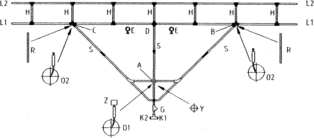
[0034] Under the condition that the power traction system and the stainless steel telescopic pipe are the same for the agricultural watering machine of the present invention, the planar sprinkling structure has multiple implementation modes.

[0035] The first embodiment is as attached figure 1 , figure 2 As shown, the water source enters the planar overall structure from K1 or K2, enters the spraying horizontal pipe L1 through the diversion water delivery pipe S, and sprays backwards and downwards, and then enters another spraying horizontal pipe L2 through multiple short water delivery pipes H to Spray below and behind. The water pipeline S is in the shape of a herringbone or a circular arc. Its purpose is not only to stabilize the structure, but the main purpose is to make the water flow smoothly, reduce the water pressure attenuation, and evenly enter the middle of the two sides of the spraying horizontal pipe L1. For downward spraying, there are multiple short water de...


PUM


Abstract

The invention relates to an agricultural irrigation device comprising a planar sprinkling structure, a dynamic traction system, and a stainless steel telescopic pipe. The device is characterized in that the water inlet of the planar sprinkling structure is connected with one end of the stainless steel telescopic pipe; the other end of the stainless steel telescopic pipe is connected with a water source; a traction power is fixedly arranged on the foremost end of the planar sprinkling structure or is fixed at a place several meters right in front of the planar sprinkling structure; a plurality rows of small holes are drilled on the back-lower parts of the sprinkling horizontal tubes of the planar sprinkling structure; the planar sprinkling structure can travel forward under the traction of the power; a controllable water pressure gauge can generate induction signals according to water pressures, and the speed of the planar sprinkling structure traveling forward can be controlled; manual control and remote control can also be realized; the planar sprinkling structure can be folded, such that the device can be easily moved and stored when not in use.

Description

technical field [0001] The agricultural watering machine of the present invention is a watering mechanical equipment for farmers to water the fields. Background technique [0002] At present, there are many kinds of anti-drought irrigation equipment, such as irrigation equipment towed by large machinery, which is suitable for large-scale farmland, irrigation equipment towed by agricultural four-wheel vehicles is easy to trample crops, and high-pressure sprinkler equipment uses circular high-pressure jetting to irrigate the ground. , not energy-saving, uneven, with dead ends, overlapping, and misappropriation troubles, drip irrigation is suitable for areas that lack rain all year round. China is a water-deficient country with poor water resources. Flood irrigation does not conform to China's national conditions. It also reduces ground temperature, makes farming inconvenient, delays crop growth, and does not save energy. These drought-resistant irrigation equipment are not sui...

Claims


Application Information

Patent Timeline
IPC IPC(8): A01G25/09
Inventor 刘碰
Owner 刘碰
Learn More