
Antenna

A technology for antennas and patch antennas, which is applied in antennas, resonant antennas, antenna parts, etc., can solve the problems of lagging development of RFID antennas and obstacles to the application of RFID technology, and achieve the requirements of size reduction, thickness reduction, and widening frequency band characteristics Effect

Inactive Publication Date: 2014-10-29
ZTE CORP
View PDF1 Cites 9 Cited by
  • Summary
  • Abstract
  • Description
  • Claims
  • Application Information

AI Technical Summary

Problems solved by technology

At present, the development of RFID antennas is seriously lagging behind, which has seriously hindered the application of RFID technology.

Method used


Image

  • Antenna
  • Antenna
  • Antenna

Examples


Embodiment Construction

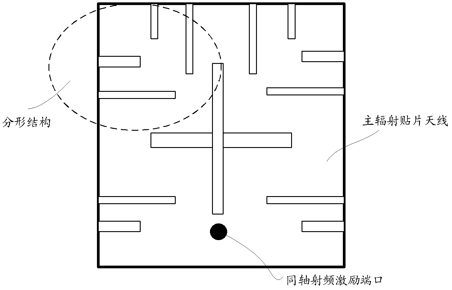
[0025] figure 1 It is a schematic diagram of the composition structure of the antenna of the present invention, such as figure 1 As shown, at least include: main radiating patch antenna ( figure 1 shown in the shaded part of the vertical bar), the first printed circuit board (PCB, Printed Circuit Board) substrate, the coaxial RF excitation port ( figure 1 shown in the shaded part of the snowflake point in the center), and the floor ( figure 1 shown in the diagonal shaded part); among them,

[0026] The main radiation patch antenna is arranged on one side of the first PCB substrate, and can be photolithographically etched on the first PCB substrate through a microstrip manufacturing process; the main radiation patch antenna is connected to the coaxial radio frequency excitation port in the first PCB substrate.

[0027] In the present invention, the main radiation patch antenna is made up of one or more fractal structures, such as figure 2 As shown, each fractal structure i...


PUM


Abstract

An antenna, comprising a primary radiation patch antenna, a first printed circuit board (PCB) substrate, a coaxial radio-frequency excitation port and a floor, wherein the primary radiation patch antenna is arranged at one side of the first PCB substrate, and is connected to the coaxial radio-frequency excitation port in the first PCB substrate; the coaxial radio-frequency excitation port is provided on the first PCB substrate, and one side of the first PCB substrate is provided with the primary radiation patch antenna, and the other side thereof is provided with the floor; and the primary radiation patch antenna is composed of one or more fractal structures. The antenna in the present invention can be applied to an RFID system of a small-scale terminal, and satisfies the reliability of the RFID system, thereby satisfying the potential demand of the current development and the future development of the RFID technology.

Description

technical field [0001] The invention relates to the technical field of near-field communication, in particular to an antenna applied to an RFID system. Background technique [0002] Radio Frequency Identification (RFID, Radio Frequency Identification) is a wireless communication technology that began to rise in the 1990s and gradually matured. It uses radio frequency signals to conduct non-contact two-way communication, automatically identify target objects and obtain relevant information data. RFID uses radio frequency signals to achieve contactless information transmission through spatial coupling, and achieves the purpose of identification through the transmitted information. The key component of the RFID system is the antenna, and the key to the practical application of RFID technology also depends on the design of the antenna. The antenna is one of the key factors affecting the reliability and other performance of the wireless communication system. It is very importan...

Claims


Application Information

Patent Timeline
Patent Type & Authority Applications(China)
IPC IPC(8): H01Q1/38H01Q1/22
CPCH01Q9/0407H01Q1/2208H01Q1/36H01Q5/378
Inventor 陈亚军沈俊程守刚
Owner ZTE CORP
Learn More