Corneal curvature measurement device based on telecentric optical path system
A telecentric optical path and curvature measurement technology, used in eye testing equipment, medical science, diagnosis, etc., can solve the problems of inaccurate corneal curvature value and difficulty in focusing on the z-axis, and achieve precise focusing and improve measurement accuracy. , to ensure the effect of measurement accuracy
- Summary
- Abstract
- Description
- Claims
- Application Information
AI Technical Summary
Problems solved by technology
Method used
Image
Examples
Embodiment 1
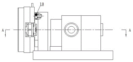
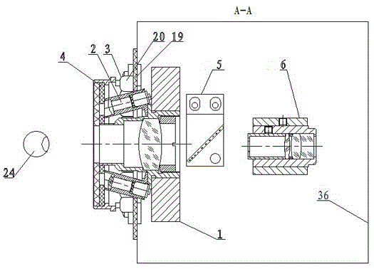
[0025] A corneal curvature measurement device based on a telecentric optical path system, such as figure 2 , it consists of objective lens device 1, light spot collimation device 2, ring lighting device 3, ring device 4, monitoring spectroscopic mirror device 5, monitoring system device 6 and base plate 36. The exit pupil of the autorefractor is located in front of the central hole of the bull ring device 4, wherein, such as Figure 4 , the objective lens device 1 comprises an objective lens holder 7, an objective lens barrel 8 and an objective lens 9, the objective lens 9 holder 7 is fixed on the base plate 36, the objective lens barrel 8 is fixed on the objective lens holder 7 by a screw 10, and the objective lens 9 is fixed by a pressure cylinder In the objective lens barrel 8; as Figure 5 There are two light spot collimation devices 2 arranged symmetrically about the center of the objective lens barrel 8, and the light spot collimation device 2 is inclined at 10 degrees...
Embodiment 2
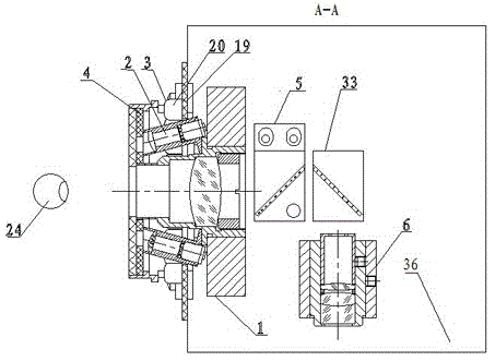
[0027] A corneal curvature measurement device based on a telecentric optical path system, such as image 3 , it is made up of objective lens device 1, spot collimation device 2, ring illumination device 3, ring device 4, monitoring spectroscopic mirror device 5, reflector device 33, monitoring system device 6 and base plate 36, when starting measurement , the human eyeball is located at the exit pupil of the automatic refractor, that is, in front of the central hole of the bull ring device 4, wherein, as Figure 4 , objective lens device 1 comprises objective lens mount 7, objective lens barrel 8 and objective lens 9, objective lens 9 mounts 7 are fixed on the base plate 36, objective lens barrel 8 is fixed on the objective lens mount 7 by screw 10, objective lens 9 is fixed by wire loop In the objective lens barrel 8; as Figure 5 There are two light spot collimation devices 2 arranged symmetrically about the center of the objective lens barrel 8, and the light spot collimat...
PUM
 Abstract
Description
Claims
Application Information
 - R&D
- Intellectual Property
- Life Sciences
- Materials
- Tech Scout
- Unparalleled Data Quality
- Higher Quality Content
- 60% Fewer Hallucinations
Browse by: Latest US Patents, China's latest patents, Technical Efficacy Thesaurus, Application Domain, Technology Topic, Popular Technical Reports.
© 2025 PatSnap. All rights reserved.Legal|Privacy policy|Modern Slavery Act Transparency Statement|Sitemap|About US| Contact US: help@patsnap.com


