Eureka AIR delivers breakthrough ideas for toughest innovation challenges, trusted by R&D personnel around the world.

Throttle structure and pressure drop device

A two-stage throttling and valve needle technology, which is applied in valve devices, valve devices for absorbing fluid energy, valve details, etc., can solve problems such as affecting product noise quality, refrigerant easily forming bubbles, affecting heat exchange efficiency, etc. To achieve the effect of reducing the possibility of turbulent vortex formation and shedding, reducing the possibility and improving heat transfer efficiency

Active Publication Date: 2017-02-08
GREE ELECTRIC APPLIANCES INC
View PDF6 Cites 3 Cited by
  • Summary
  • Abstract
  • Description
  • Claims
  • Application Information

AI Technical Summary

Problems solved by technology

[0003] In the traditional throttling structure, the pressure difference before and after the throttling is large, the flow velocity of the refrigerant drops rapidly along the flow channel, and more kinetic energy dissipated by the refrigerant is converted into heat energy, so that the liquid refrigerant is easy to form bubbles and generate gas. Liquid two-phase state, affecting heat transfer efficiency
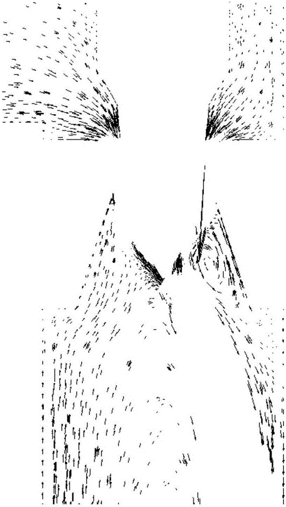
At the same time, a pulsating turbulent vortex is easily formed downstream of the throttle hole, accompanied by the phenomenon of turbulent vortex shedding, such as Figure 3-a As shown, resulting in corresponding noise problems, affecting the noise quality of the product

Method used


Image

  • Throttle structure and pressure drop device
  • Throttle structure and pressure drop device
  • Throttle structure and pressure drop device

Examples


Embodiment Construction

[0018] The present invention will be described in detail below in conjunction with examples. It should be noted that, in the case of no conflict, the embodiments in the present application and the features in the embodiments can be combined with each other.

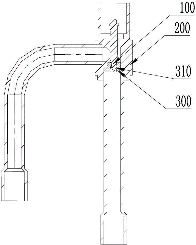
[0019] see figure 2 , an embodiment of the throttling structure provided by the present invention includes a valve needle 100, a valve body 200 and a valve seat core 300, the valve seat core 300 is fixed on the valve body 200, and a smooth transition channel is arranged inside the valve seat core 300 Hole 310. The upper end of the valve needle 100 is cylindrical, the lower end is conical, the through hole 310 is larger in the middle and smaller at the two ends, and the cross-sectional area of ​​the upper and lower ends is smaller than the cross-sectional area of ​​the middle. The shape of the through hole 310 matches the shape of the valve needle 100 , and the valve needle 100 can be inserted into the through hole 310 ...


PUM


Abstract

The invention discloses a throttling structure and a pressure drop device. The throttling structure comprises a valve needle, a valve body and a valve seat core, wherein the valve seat core is fixed to the valve body. A through hole in smooth transition is formed in the valve seat core and is matched with the valve needle in shape. The valve needle is inserted into the through hole and forms a throttling round ring with the through hole. The pressure drop device comprises the throttling structure. The throttling structure and the pressure drop device achieve two-stage throttling, and therefore good and smooth transition of the differential pressure change before throttling and after throttling is guaranteed, the possibility of two phase caused when liquid refrigerating fluid flows through a throttling hole is reduced, and the heat exchange efficiency of a system is improved. Meanwhile, the possibility of turbulence vortex forming in the downstream of the throttling hole and dropping is reduced, related noise problems are avoided, and the noise quality of products can be improved.

Description

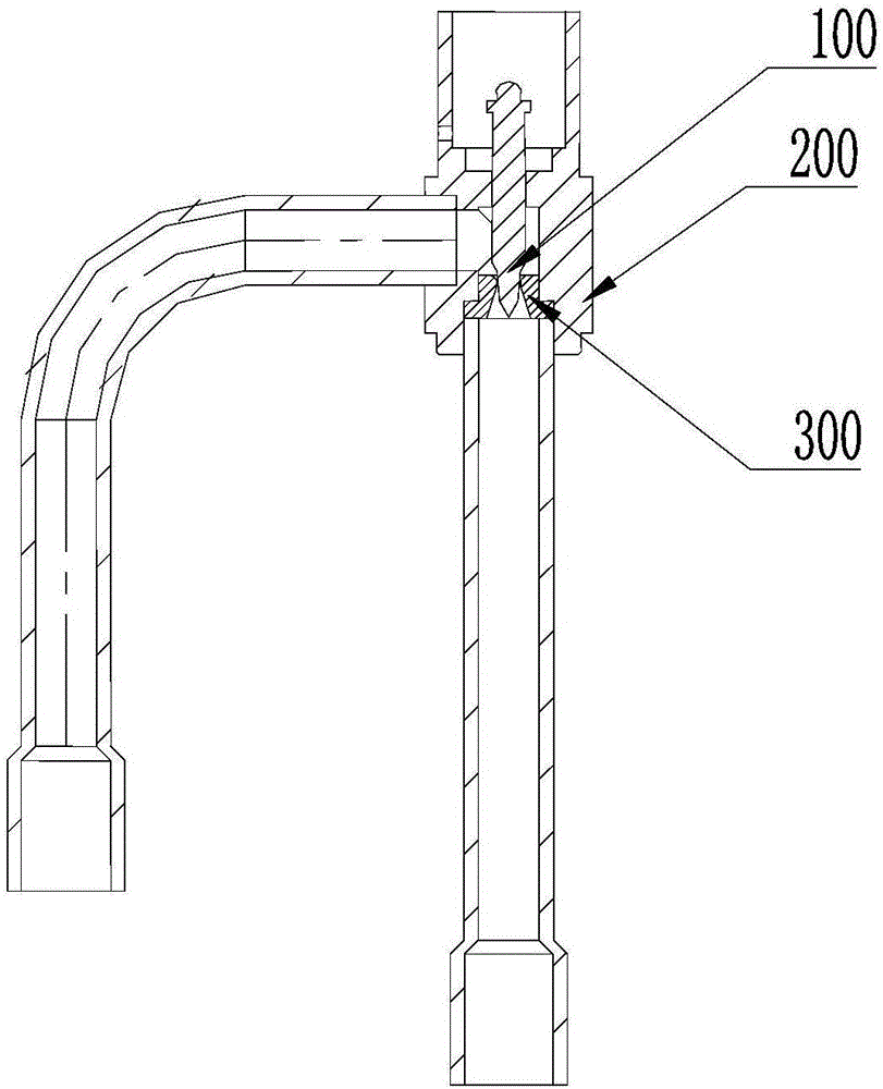
technical field [0001] The invention relates to the technical field of throttling and pressure reduction, in particular to a throttling structure and a pressure drop device. Background technique [0002] The throttling structure of the traditional electronic expansion valve is as follows: figure 1 As shown, the entire throttling structure is mainly composed of a valve needle 100, a valve body 200 and a valve seat core 300. By adjusting the upper and lower positions of the valve needle 100 and adjusting the size of the throttling ring hole, throttling with different openings is realized. The fluid enters the cavity of the valve body 200 laterally, passes through the narrow ring hole formed by the valve needle 100 and the valve seat core 300, and flows out vertically, realizing a first-stage throttling. [0003] In the traditional throttling structure, the pressure difference before and after the throttling is large, the flow velocity of the refrigerant drops rapidly along th...

Claims


Application Information

Patent Timeline
Patent Type & Authority Patents(China)
IPC IPC(8): F16K47/04F16K47/02
CPCF16K47/04F16K47/08
Inventor 周军罗荣海王继承杨阳周金冶张馨云段向春
Owner GREE ELECTRIC APPLIANCES INC
Why Eureka
Eureka Blog
Learn More