Tyre inflation device

A technology for inflating equipment and tires, applied in tire installation, tire parts, vehicle parts, etc., can solve problems such as unfavorable space requirements, and achieve the effect of low cost and small space requirements

Active Publication Date: 2014-10-22
SCHENCK ROTEC GMBH
View PDF9 Cites 6 Cited by
  • Summary
  • Abstract
  • Description
  • Claims
  • Application Information

AI Technical Summary

Problems solved by technology

Here, it is disadvantageous with regard to the space requirement when installing more than three inflation rings on the carrier plate

Method used


Image

  • Tyre inflation device
  • Tyre inflation device
  • Tyre inflation device

Examples


Embodiment Construction

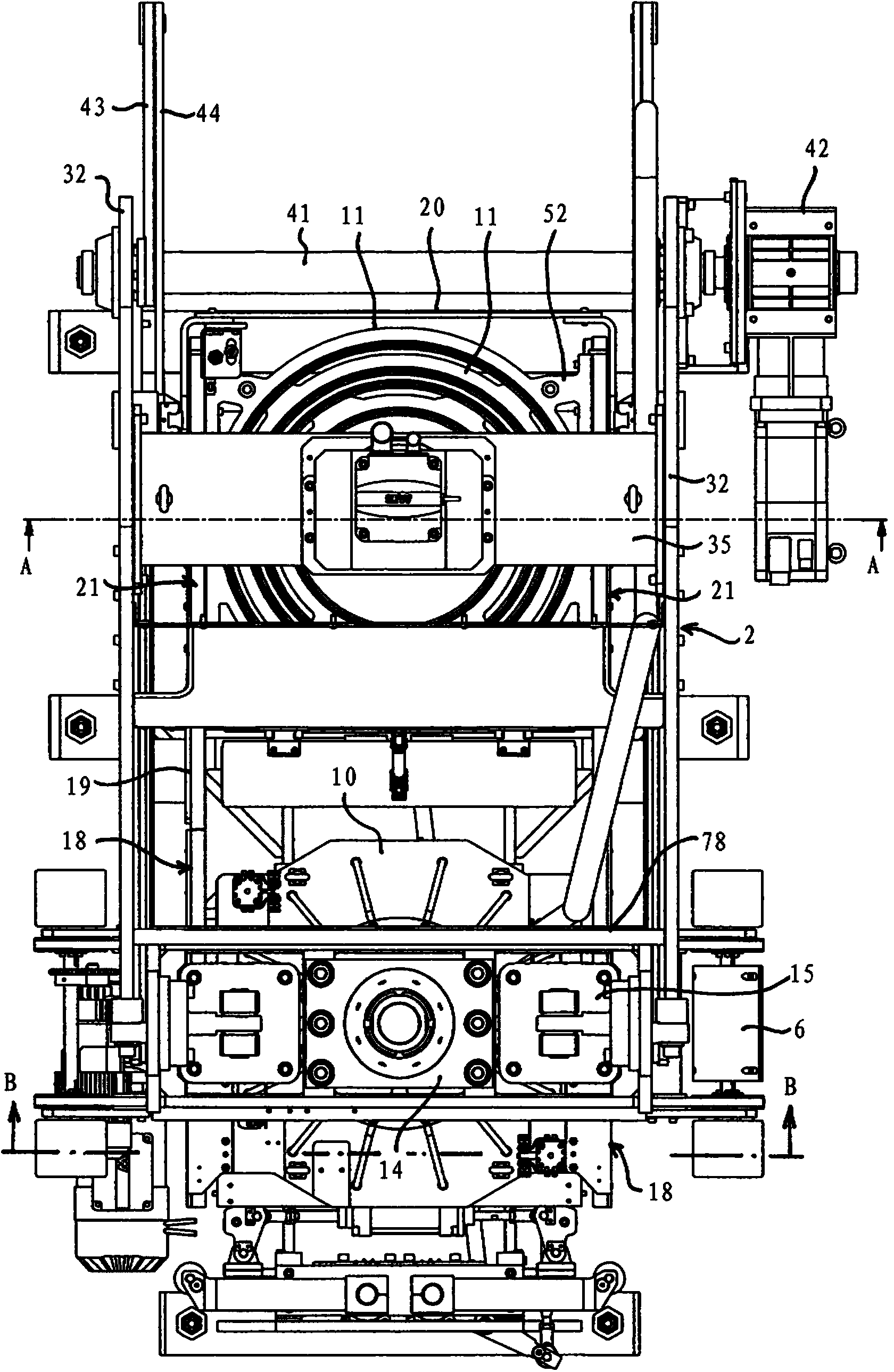
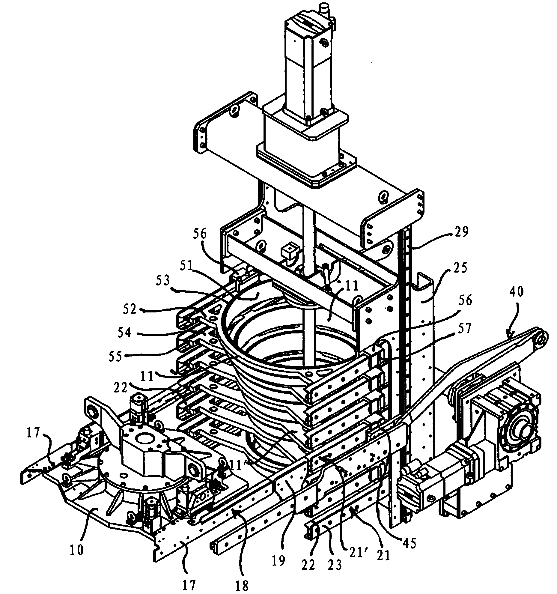
[0035] figure 1 A tire inflation device 1 is shown with a frame 2 , whose front side wall has been cut away in the direction of the view, in order to be able to clearly show details of the storage chamber 3 located behind. The tire inflation device 1 comprises a tire inflation cap 4 as well as a supporting and sealing device 5 which transports a wheel with pre-assembled tires by means of a transport device 6 and rests against the supporting and sealing device 5 by means of one side. On the plate-like platform 7 of. A tire fitting station, in which tires are mounted on wheel rims, is usually connected upstream of the tire inflation system 1 .

[0036] The bearing and sealing device 5 as well as the conveying device 6 are already known from EP1125772B1, the relevant contents are therefore incorporated here. The bearing and sealing device 5 consists of several parts. The plate-shaped platform 7 is divided into several parts and is supported on the machine frame 2 . The diamet...


PUM


Abstract

In a tire inflating device having a machine frame (2), a tire filling bell (4) arranged on the machine frame (2) and a supporting and sealing device (5) for sealing a filling chamber. The tire filling bell (4) is comprised of a filling plate (10) and a separate filling ring (11). A magazine (3) has a magazine rack (20) and magazine guides (21) lying in a plurality of parallel planes, each of said guides being able to hold a filling ring (11, 11′) mounted so that it can move. The magazine rack (20) and the filling plate (10) can be moved with respect to each other into a plurality of transfer positions in the direction of the axis of rotation. The magazine guide (21) in each case is connected to a filling plate guide (18) arranged on the filling plate (10) in said transfer positions. A filling ring (11) which is located in the magazine guide (21) arranged in the transfer position can be conveyed by a conveying device (40) into a filling plate guide and a centered position on the filling plate (10).

Description

technical field [0001] The invention relates to a tire inflation device capable of conveying a wheel consisting of a rim and a tubeless tire mounted on the rim, the tire inflation device having a tire inflation cage and a sealing device for sealing the installation space, wherein The tire inflation housing consists of an inflation plate movable along the axis of rotation of the wheel and a separate inflation ring which can be selected from a number of mutually interchangeable inflation rings of different diameters and which can be moved to align with the axis of rotation. center-aligned position, wherein the inflatable ring placed at the central position can rest against the inflatable plate by the first edge and can move together with it, and wherein the inflatable ring placed at the central position faces away from the inflatable plate The second edge can bear against the side of the tire. The invention also relates to a method of inflating a tubeless tire mounted on a rim....

Claims


Application Information

Patent Timeline
Patent Type & Authority Applications(China)
IPC IPC(8): B60S5/04
CPCB60C25/145B60S5/04
Inventor M.罗加拉M.奥特维恩A.佩尼尔特
Owner SCHENCK ROTEC GMBH
Why Eureka
Try Eureka