


Quick Research
Generate reliable direction feasibility study reports for your R&D in just a few steps.

Technical Q&A
Discover and master advanced knowledge NOW. Basics, ideas, possibilities, all at once.

Find Solutions
As an expert in R&D theories, this can generate solutions to your technical problems instantly.

Evaluate Feasibility
Analyze your overall solution with one click, know your potential R&D risks in advance.

Monitor Landscape
Get weekly tech updates, stay abreast of the latest tech innovations and key insights.
Light-emitting diode control circuit
A light-emitting diode and control circuit technology, which is applied in energy-saving control technology, electric lamp circuit arrangement, light source, etc., can solve the problems of light-emitting diode control circuit 100 that cannot be applied to lightweight electronic products, volume restrictions, etc., to reduce the implementation area and volume. , the effect of avoiding burning
- Summary
- Abstract
- Description
- Claims
- Application Information
AI Technical Summary
Problems solved by technology
Method used
Image

Examples
Embodiment Construction
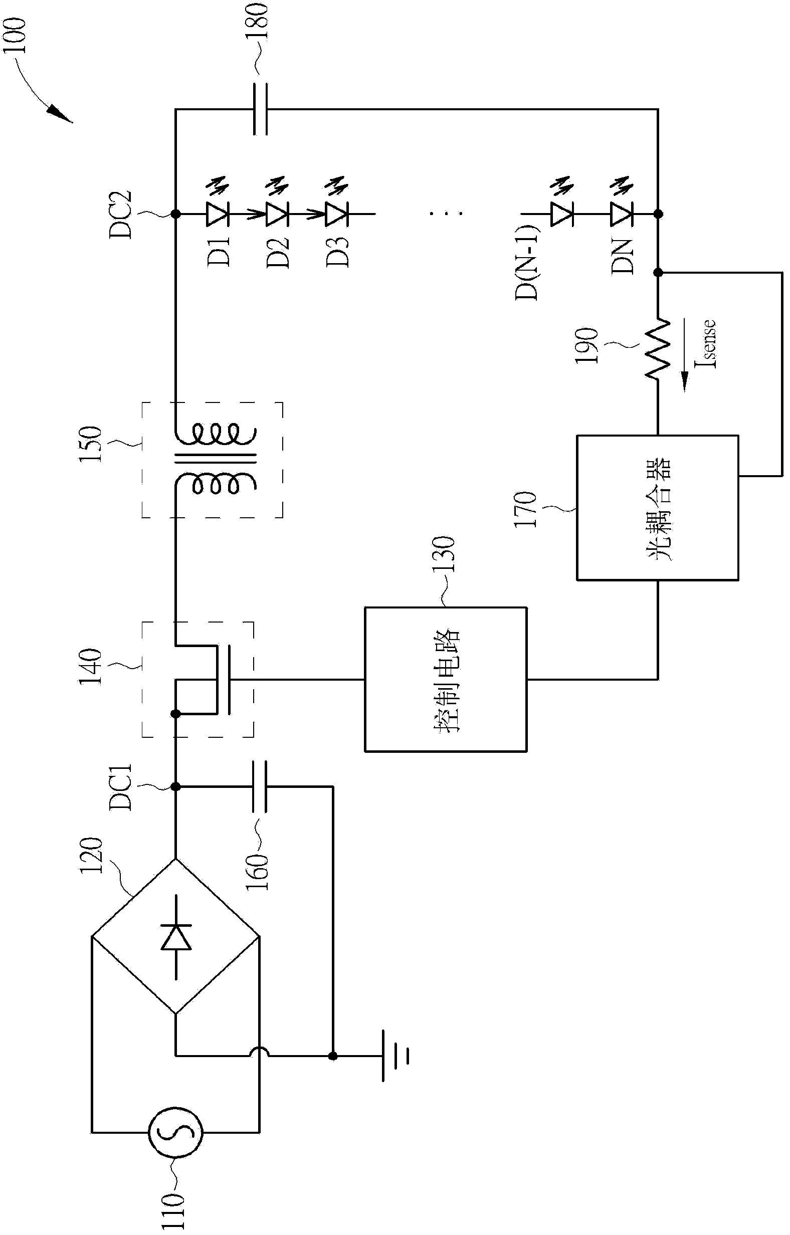
[0023] In order to solve such as figure 1 The light emitting diode control circuit 100 of the known technology occupies too much area. The present invention discloses a light emitting diode control circuit that does not require various large-area passive components used in the known technology and uses fixed power.
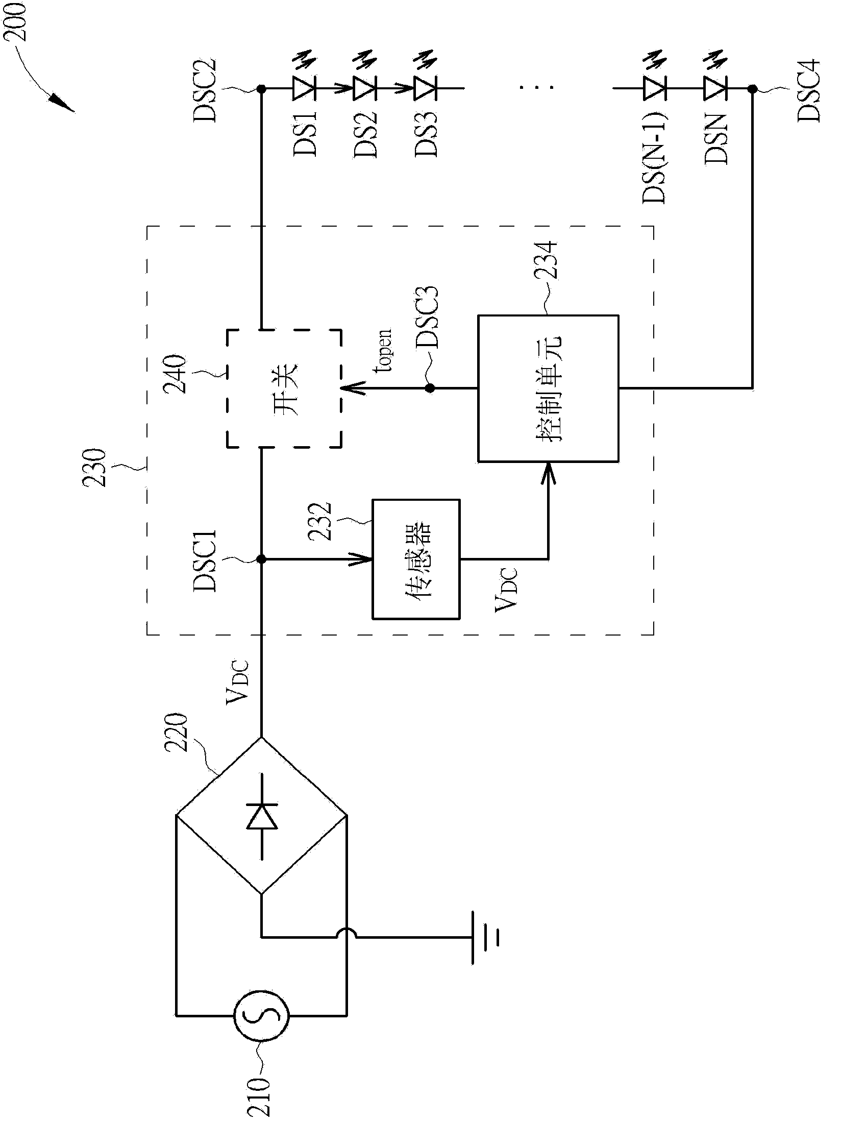
[0024] see figure 2 , which is a schematic diagram of the LED control circuit 200 according to the present invention. Such as figure 2 As shown, the LED control circuit 200 includes an AC power source 210, a bridge rectifier 220, a control circuit 230, and a group of LEDs DS1, DS2, DS3, . . . , DS(N-1), and DSN connected in series.
[0025] The first terminal of the AC power supply 210 is coupled to the first terminal of the bridge rectifier 220, the second terminal of the AC power supply 210 is coupled to the second terminal of the bridge rectifier 220, and the AC power supply 210 and the bridge rectifier 220 are used for The node DSC1 at the output of the b...
PUM
 Abstract
Description
Claims
Application Information
 - R&D Engineer
- R&D Manager
- IP Professional
- Industry Leading Data Capabilities
- Powerful AI technology
- Patent DNA Extraction
Browse by: Latest US Patents, China's latest patents, Technical Efficacy Thesaurus, Application Domain, Technology Topic, Popular Technical Reports.
© 2024 PatSnap. All rights reserved.Legal|Privacy policy|Modern Slavery Act Transparency Statement|Sitemap|About US| Contact US: help@patsnap.com