A device for improving output power of microstrip fast-edge double-exponential pulse source

A technology of output power and pulse source, applied in connection devices, electrical pulse generator circuits, waveguide-type devices, etc., can solve the problems of low withstand voltage, broadband signal reflection and waveform distortion, affecting the stability of output pulses, etc.

Active Publication Date: 2017-01-04
PEOPLES LIBERATION ARMY ORDNANCE ENG COLLEGE
View PDF2 Cites 0 Cited by
  • Summary
  • Abstract
  • Description
  • Claims
  • Application Information

AI Technical Summary

Problems solved by technology

Moreover, in order to reduce the loop inductance, increase the steepness of the output pulse front, and make it more miniaturized, many semiconductor high-speed switches are made of chip type, and the pulse source made of this type of chip switch is generally a high-frequency microstrip However, compared with the spark gap switch, this type of semiconductor switch has a low withstand voltage value and low output pulse power, so it is very important to increase the output power of this type of pulse source
[0003] At present, there are two ways to increase the output power of this type of pulse source. One is to use more stages of Marx circuit cascading to increase the output voltage of the pulse source itself. However, too many stages will inevitably affect the output pulse. stability, and in the electromagnetic compatibility test, high stability is the primary indicator; the other is to use a power combiner for power synthesis of multiple pulse circuits, but because the output pulse of this type of pulse source is a fast edge pulse, With nanosecond or sub-nanosecond rising edge, the spectrum covers DC to GHz or even a wider range, while ordinary single-cell power combiners only have a good synthesis effect on narrowband signals, and cause large reflections on broadband signals and waveform distortion

Method used


Image

  • A device for improving output power of microstrip fast-edge double-exponential pulse source

Examples


Embodiment Construction

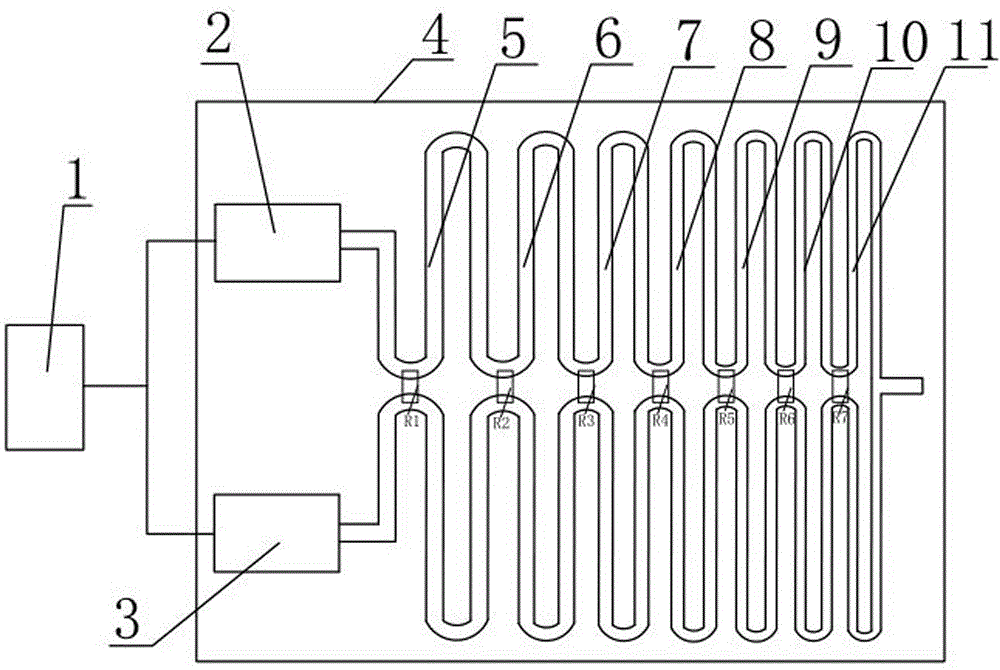
[0015] Such as figure 1 As shown: it includes a synchronous trigger circuit 1, a first pulse source 2, a second pulse source 3 and a power combiner, the first pulse source 2 and the second pulse source 3 are the same, and the output terminals of the synchronous trigger circuit 1 are respectively Connected to the input ends of the first pulse source 2 and the second pulse source 3, the power combiner is a substrate 4 with two signal transmission lines, and the signal transmission lines are two The same microstrip line, the two microstrip lines are symmetrically arranged, and the two microstrip lines have a common output terminal, and the first pulse source 2 and the second pulse source 3 are also arranged on the base On chip 4, the output terminals of the first pulse source 2 and the second pulse source 3 are respectively connected to the respective input terminals of the two microstrip lines, and the impedance of the respective input terminals and the common output terminals o...


PUM


Abstract

The invention discloses a device for increasing the output power of a microstrip fast-edge double-exponential pulse source, and relates to the technical field of microwave electronics. It includes a synchronous trigger circuit, a first pulse source, a second pulse source and a power combiner, the output terminals of the synchronous trigger circuit are respectively connected to the input terminals of the first pulse source and the second pulse source, and the power combiner has two signals The substrate of the transmission line, the signal transmission line is two microstrip lines arranged symmetrically on the substrate, and the two microstrip lines have a common output terminal, and the first pulse source and the second pulse source are also arranged on the same On the above-mentioned substrate, the output ends of the two microstrip lines are connected to the respective input ends of the two microstrip lines, and the impedance of the two microstrip lines matches the pulse source and the common output end. The multi-section sub-line body whose impedance value becomes larger in turn, and an isolation resistor is also provided between the two microstrip lines. The device realizes the high-isolation, high-efficiency and low-reflection synthesis of two synthetic signal lines.

Description

technical field [0001] The invention relates to the field of microwave electronics technology. Background technique [0002] In the electromagnetic compatibility test, it is necessary to develop a pulse source to simulate the interference source, and to evaluate the electromagnetic pulse immunity or sensitivity of the equipment or device, the peak voltage (or peak power) of the pulse source output pulse, stability, repetition Frequency, leading edge steepness, pulse width, etc. are all key indicators of the pulse source. In recent years, due to the advantages of high stability, fast switching speed, high repetition frequency, and small size, semiconductor solid-state switches have been extensively studied in the field of pulse power. Moreover, in order to reduce the loop inductance, increase the steepness of the output pulse front, and make it more miniaturized, many semiconductor high-speed switches are made of chip type, and the pulse source made of this type of chip swit...

Claims


Application Information

Patent Timeline
Patent Type & Authority Patents(China)
IPC IPC(8): H03K3/02H03K19/0175H01P5/12
Inventor 周星赵敏王庆国杨清熙范丽思张希军程二威潘晓东
Owner PEOPLES LIBERATION ARMY ORDNANCE ENG COLLEGE
Why Eureka
Try Eureka