Common-ground type power factor correction circuit

A power factor correction and circuit technology, applied in output power conversion devices, electrical components, high-efficiency power electronic conversion and other directions, can solve the problems of public grid voltage waveform distortion, pollution of grid environment, power quality degradation, etc., and achieve low circuit cost. , to ensure the effect of power quality and high power density

Active Publication Date: 2020-09-18
HANGZHOU LUNTEK TECH
View PDF5 Cites 0 Cited by
  • Summary
  • Abstract
  • Description
  • Claims
  • Application Information

AI Technical Summary

Problems solved by technology

For example, some non-linear electrical equipment is also connected to the power grid, and the harmonic current generated by it is injected into the power grid, which distorts the voltage waveform of the public power grid, seriously pollutes the environment of the power grid, causes a decline in power quality and even seriously threatens the connection Safe operation of electrical equipment connected to the grid

Method used


Image

  • Common-ground type power factor correction circuit
  • Common-ground type power factor correction circuit
  • Common-ground type power factor correction circuit

Examples


Embodiment Construction

[0012] The specific implementation of the present invention will be further described in conjunction with the accompanying drawings and examples, but the protection scope of the present invention is not limited thereto. It should be pointed out that, if there are processes or symbols that are not specifically described in detail, those skilled in the art can understand and implement with reference to the prior art.

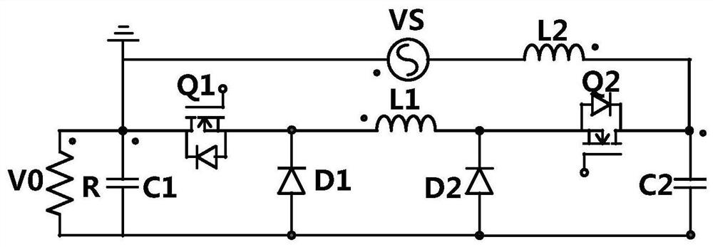
[0013] The basic topology of the present invention is as figure 1 As shown, for the convenience of analysis, the devices in the circuit structure are all ideal devices.

[0014] A novel power factor correction topology provided by the present invention specifically includes a first switching tube Q1, a second switching tube Q2, a first diode D1, a second diode D2, a first inductor L1, and a second inductor L2 , capacitor C1, capacitor C2, sinusoidal AC source VS and load R.

[0015] The specific connection mode of the circuit of the present invention is as follo...


PUM


Abstract

The invention discloses a common-ground type power factor correction circuit. The circuit comprises a first switching tube Q1, a second switching tube Q2, a first diode D1, a second diode D2, a firstinductor L1, a second inductor L2, a capacitor C1, a capacitor C2, a sine alternating current source VS and a load R. The circuit adopts a 'back-to-back' type double-BUCK circuit structure and works in a BOOST mode and a BUCK-BOOST mode in a time-sharing manner, common ground of an alternating current source end and a load end is realized, the circuit cost is low, the power density is high, and meanwhile, the electric energy quality of the input side of a power grid is ensured.

Description

technical field [0001] The invention belongs to the field of power electronics, and in particular relates to a common-ground power factor correction circuit. Background technique [0002] With the economic development of our country, the modern industry has also developed rapidly, and various converter equipment are used more and more, and the capacity is also increasing. For example, some non-linear electrical equipment is also connected to the power grid, and the harmonic current generated by it is injected into the power grid, which distorts the voltage waveform of the public power grid, seriously pollutes the environment of the power grid, causes a decline in power quality and even seriously threatens the connection Safe operation of electrical equipment connected to the grid. Therefore, in order to limit the pollution of high-order harmonics to the power grid, electrical organizations at home and abroad have formulated relevant standards and solutions. At present, the...

Claims


Application Information

Patent Timeline
Patent Type & Authority Applications(China)
IPC IPC(8): H02M1/42
CPCH02M1/4208H02M1/4225Y02B70/10
Inventor 何远彬何加劲冯浩
Owner HANGZHOU LUNTEK TECH
Why Eureka
Try Eureka